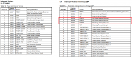
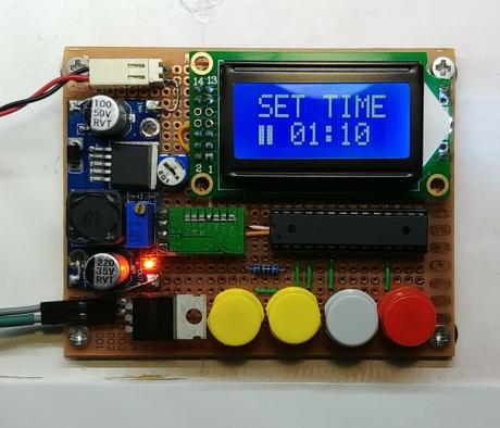
I have a few atmega8 laying around, bought over ten years ago. Powered by, pretty much, the same 8bit MCU like what’s in Arduino UNO, except, it has only 8k of flash and 1k of ram. It is, kinda, on a par with attiny85. There is only one catch, it doesn’t support PCINT like atmega328 does. An attiny85 would do this job perfectly, of course I would have to use i2c adapter for LCD0802 but, meh.
It was so cheap at the time I bought them. After over 10 years, it still works just fine. It just happened that I need a timer for my pcb UV-exposure lamp. So, I made use of them instead of let them laying in the bin forever. I also happened to have a spare LCD0802 that I have no use at all. 8 characters 2 lines LCD is quite small for any projects but it’s perfect for this timer. Then find a suitable BJT or MOSFET to handle high current for the UV LEDs.
Things need to prepare:
- - Arduino IDE 1.8.9 at the time of this entry.
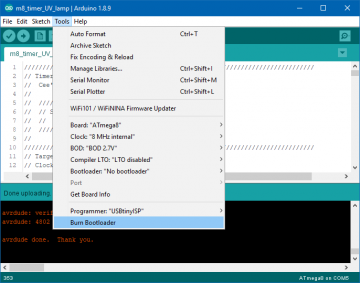
- - Arduino MiniCore https://github.com/MCUdude/MiniCore
- - Atmega8 or atmega328 + 16Mhz xtal + 2pcs of 22pF
- - LCD0802 + 10k trim pot (for contrast)
- - UV led strip (depend on board size)
- - DC to DC buck converter that can handle high current.
- - Another DC buck converter for atmega8
- - IRFZ44N (N-channel mosfet )
- - 5v active buzzer (optional)
- - DC connector (male/female)
- - 4 tactile buttons
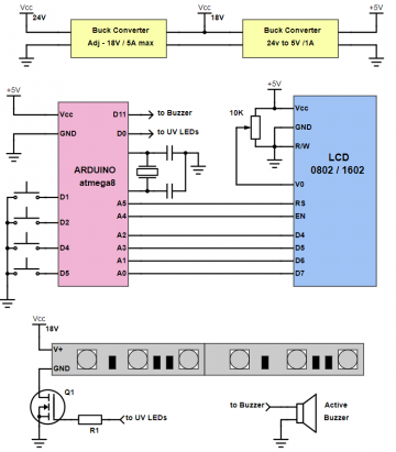
The Circuit - atmega8
The Arduino circuit is striped naked to just a crystal and 2 capacitors. You can even remove it if you choose to use internal osc 8Mhz which is, somewhat, not as accuracy as a crystal. But for this project, the timing precision is not really important, you know, expose your pcb for 1m20s or 1m24s doesn’t make a different. Internal OSC of atmega8 is within +/-3% of nominal frequency at 25°C (datasheet page 30).
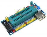
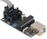
You will need a development board with a zif socket and a programmer to program this little puppy. Just search ebay for “atmega88 development board” and “USBtinyISP”, about ~12 AUD total (free ship). And then you can work with atmega328 and alike with just bare bone DIP28 chip without anything attach.
Some unsoldered development kits come without ISP 10pin ribbon cable. This maybe the downside, that you have buy or make one yourself. Anyway, 10pin ISP connector is quite useful for other old-school 8051s, thus, just spend another 2 AUD on “10p ribbon cable” along the way checking out. Nothing can go wrong here.
So, back to the circuit. You don’t need either UART, I2C, SPI then you can use virtually any pin for any function that you find comfortable when doing PCB for it. For me, this is just an hour for the hardware and another hour for the code. So perfboard all the way to go.
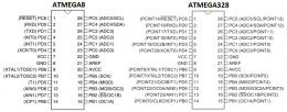
Atmega8 is quite old and just little bit different than atmega328. Fortunately, the pinout is compatible between 8bit atmega family of the same type of package. That is you can probably drop in atmega8 into atmega328 board and it just works if you don’t need much flash memory or RAM like this project.
UV LED strip
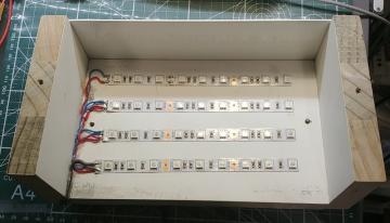
I use mainly for making small size PCB, usually 150×100mm. I just need about 4 strips, each strip has 9 LEDs make it total 36 UV LEDs. Each LED has a 240 Ohm resistor in series.
The UV LED strip is rated for 12V. That is in normal condition for looooong term, say 50k hours or so. I don’t think I need it last that long. At 12V, the whole thing, 36 LEDs of 5050, consumes aprox 0.34A. It is around 9mA for each LED. Well, normally a typical “super bright” LED rated at 20mA for a normal condition!
Then I just “crank” the voltage “a little bit” to 24V for experiment. It took approx 2A and the LEDs became warm quite fast but not too hot so I could touch it. Alright, that makes a single 5050 LED consumes about 55mA, quite at the break limit of the LED at this size. OK, then I just reduced the voltage down to a more comfortable level. I choose 18V to be exact, that makes 1.15A total and approx 32mA across each LED, a reasonable value for this size of LED. Hence the odd voltage value of 18V. The 19V laptop adaptor works just fine for this matter.
By increasing voltage to 1.5 time of manufacturer rating, I get almost 3 times intensity of UV light of these LEDs, of course some power converts to heat but still quite effective. I don’t care about the life time of these LEDs in the state of over-current-ish. I used only 60cm of 5m. It costed me around 15 AUD for 5m, no big deal if I have to replace the LED strip after a few months or so.
Controlling LED strip
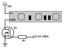
For controlling LED strip this size (0.6m - 36 LEDs), you just use a simple electronic switch that capable of handling 2A. For dead simple, a low-side switch with a resistor and a N-channel mosfet, is used. IRFZ44N is what I have for example, it is not a logic level mosfet. At 5V Vgs, it doesn’t fully on and there is some drop on the output current from 1.15A down to 1A, still good driving it directly from digital pin of atmega8. If you prefer to stay on the safe side, just use a logic level mosfet such as IRLZ44N instead. No worries what so ever.
Just a note: MOSFET is a voltage control device and BJT is a current control device.
Current goes through collector of BJT is controlled by current goes through base with the ratio of Ic = Ib*hfe. In many cases hfe = 300 for low power BJT but high power BJT has hfe about 30 only. So, you need 2A at collector you will need 2A/300 = 6.6mA at base. Therefore, R_base = (5V - 0.6V) / 6.6mA = 660 Ohms. But in most case, you will need to attach a small heatsink on the BJT because it will get hot quite fast.
In contrary, you don’t need to force current go through the gate of mosfet, so a high value resistor like 10k would works just fine. But beware of gate capacitance of a mosfet (a few nano farad), it will form RC filter that slow down risen time or fallen time of your pulse. But when using it as a simple switch like this project, it doesn’t matter at all if it switch on/off a few micro second late. one more thing, make sure to use mosfet that has low gate-source threshold voltage as some MOSFETs just don’t turn on at 3.3V logic even in datasheet says it turns on at 3V.
Controller board - Perfboard to go
This is quite simple, much more like breadboard stuff, so I just used perfboard and soldered everything on it. No need for fancy stuffs like debounce cap for these buttons.
You might think the board of this size 70×90mm is quite full of components, but take a look closer, you will see the arduino based circuit is just a single atmega8, no crytal and no caps. You want to use a DIP socket instead of soldering the atmega8 directly on the perfboard since you have to take it out for possible firmware “upgrade” anyway.
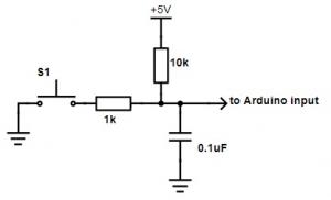
For the buttons, some people love to solve the bouncing problem of buttons in the hardware. Yeeeeah, it’s nice touch but not necessary since you can do it in code.
This setup is just a simple RC filter which gives you about 2.3ms before recover to 5V and approx 1ms before it recovers to 3V to register a HIGH level on a digital pin. Change the cap to 0.47uF will get you around 5ms debounce. Typically it would be alright for most of the case.
You might ask why don’t I use an encoder for simplicity? Yeah, it is nice to have knob(s) but ffs those cheap rotation encoders are trash, literally. If you have a 3D printer with encoder knob on the LCD you will know what I mean. Firstly, you need to spend quite some large amount of MCU clocks to handle encoder at real-time to get it run smoothly. Secondly, it backslashes like a once for a few rotations. It’s very annoying. Only the high-end encoders that use optical sensor is worth to use, IMHO, you can find them in gaming mouse for example. For something simple like this project I would like buttons, simple tactile buttons, thank you very much.
Coding
You don’t have to follow exactly my circuit, I just found it convenience while putting components on the board and use the digital pin closest to the LCD or the buttons, no fussy on picking the pins on atmega8 at all.
The only 2 libraries you need to include are for the LCD and for reading/writing EEPROM. Yes, it remembers the last dial setting you used.
The code is about 260 lines and many of them are comments or just a single bracket. Basically the main loop is alternative between Running, i.e. turn on lamp, or not Running, i.e. turn off lamp. There are 2 while loops that traps the processor. Between 2 while loops are the code for display message on the LCD.
//	///////////////   ////////////////
//	// SET TIMER //   //  LAMP ON   //
//	//   00:00   //   //  > 00:59   //
//	///////////////   ////////////////

// display dial setting and change
// turn off lamp

while(!bRunning) // lamp off - change time dial
{
    // read buttons for time dial setting...
}

// display timer count down
// turn on lamp

while(bRunning) // lamp on - time tick
{
    // sleep, count down, read stop button...
}
Debouncing button in code
There are some very effective code to debounce buttons that floating somewhere on the internet. For the simplicity I use a dirty trick to do it.
    if (digitalRead(RESET)==LOW)
    {
      while(digitalRead(RESET)==LOW) delay(80);
      reset_timer();
    }
There is no implement of debounce time to determine repeat of action. You won’t get the same effect like repeat rate when press-n-hold a key on PC anyway. This code just traps the flow for 20ms if button down event is detected the second, the third till the n time, then it let the flow continue if the button released.
Wrap it up
This project demonstrates on how you can make project out of just a single atmega328 / atmega8. You pretty much can do the same for attiny family. No need to stick a fancy Arduino UNO board inside your project.
For 36 LEDs like my setup, it takes just 1m20s for the photoresistive to be ready for developing. And that result is with 4mm glass on top of the board to press down. Not bad at all if you compare to fluorescent UV lamp setup. Maybe I can reduce the exposure time to 1min or 40s, not sure if it helps but for now, I have to leave my board in baking soda for over 20mins for it to take away the un-exposed photoresistive. Tried with sponge and finger, it sped up the process but also peeled away some small exposed areas. So, just leave it in the baking soda bath for half an hour then.
Here is the Arduino code [attach=downloads/m8_uv_lamp_timer/m8_timer_UV_lamp.ino]m8_timer_UV_lamp.ino[/attach]
And the lamp in action
Update 21/8/2019:
Lately, I ditched the 4mm glass and put the film directly on the board. It was because most of the boards were not really flat, they were bulging in the middle but the negative film sticks to the glass, hence, sometime the results are very bad in the corner. So that without the glass on top, I just need to spray some water on the film then apply to the board. Water keeps the film stick to the board quite well and it doesn’t absorb UV light as much as 4mm glass does.
Doing so, I have to reduce exposure time to only 30s because the old time dial, 1m20s, would be over exposure which results in failing to develop.
Another note is that, I changed develop agent into cleaning soda (woolworths brand). The old one, Mckenzie’s Bi Carb Soda, failed me miserably. I had no idea why. Cleaning soda is more aggressive so that I have to use sponge and wipe very gently at the un-cured area instead of dunking the whole board into developing solution like I did before. I need to do more experiment to find out the best recipe. Maybe for another blog entry.

