This entry is for someone that having basic electronics knowledge and want to understand how to control led matrix using Arduino UNO.
How do you control a led matrix?
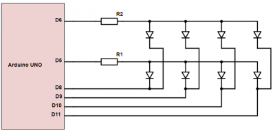
Lets start with the basic: controlling 1 row of single-color LEDs
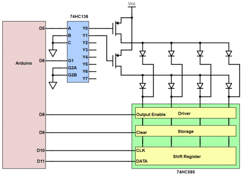
Easy stuff, right? Just put D5 to HIGH and D8-D11 to LOW to light up each individual LED.
uint8_t screen_buffer; // we need only 4 bits out of 8 bits

void setup(){
  pinMode(5, OUTPUT);
  pinMode(8, OUTPUT);
  pinMode(9, OUTPUT);
  pinMode(10, OUTPUT);
  pinMode(11, OUTPUT);

  screen_buffer =  0b00001010; //Led1 to 4 = OFF, ON, OFF, ON
}

void loop(){
  // do nothing else than light up the LEDs after some specific time
  digitalWrite(5, HIGH); // select this row

  digitalWrite(8,  (~screen_buffer & 0b00000001)   ); // LED1
  digitalWrite(9,  (~screen_buffer & 0b00000010)>>1); // LED2
  digitalWrite(10, (~screen_buffer & 0b00000100)>>2); // LED3
  digitalWrite(11, (~screen_buffer & 0b00001000)>>3); // LED4

  delay(42); // 1/24s = 42ms, let it stays for 42ms then refresh
}
Note:
- * I use binary format for easy to understand of bitwise operation, you can use hex or decimal instead, eg: 0b0001010 = 0×0A = 10
- * ~screen_buffer = inverse bits on screen_buffer, eg: 0000 1010 –> 1111 0101
- * & 0b00000001 = masking the least significant bit (LSB)
- * >>3 = shift right 3 bit, eg: 0000 x000 –> 000 000x which result is equal to boolean value of 1 or 0
The only problem is Arduino UNO digital pins only capable of driving 40mA so that without current limiter R1 you probably fry your Arduino. R1 can be calculated roughly = (Vcc - V_led) / max_current. Let’s play safe, just use half of maximum current of IO pins and ignore V_led, which results in higher R1 and lower current through the LEDs. Say 5v/20mA = 250ohm, you can choose 330ohm or 470ohm which won’t make a noticeable difference. But hey, when you light up the whole row, each LED will become dimmer as each of them gets only 1/4 of the total current (assuming you are using the same LED).
This configuration is similar to common anode you probably see in 7-seg LED.
You will also need a buffer, like a screen image, to store the LED status data. For 4 Led array like that, you will need just about 4 bits (half of a byte).
Okay, let’s add another row.
Thing gets a little bit complex now, but still easy stuff as long as you light up one ROW at a time. You might ask, if I light up one row at a time, I can only see one row which won’t make up an image I want to display. Well that is true, if you are switching row pretty slow. But if you switch row fast enough, like 24 frame/s, you will see a full image without flickering. That is 1 frame for 1/24 second and each row is 1/48 second or roughly 21ms.
uint8_t screen_buffer; // we need 2x4 bits

void setup(){
  pinMode(5, OUTPUT);
  pinMode(6, OUTPUT);
  pinMode(8, OUTPUT);
  pinMode(9, OUTPUT);
  pinMode(10, OUTPUT);
  pinMode(11, OUTPUT);

  screen_buffer =  0b01011010;
  //Row1 = OFF, ON, OFF, ON // 4 bit on the right
  //Row2 = ON, OFF, ON, OFF // 4 bit of the left
}

void loop(){
  // select row 1
  digitalWrite(5, HIGH);
  digitalWrite(6, LOW);

  digitalWrite(8,  (~screen_buffer & 0b00000001)   ); // LED1
  digitalWrite(9,  (~screen_buffer & 0b00000010)>>1); // LED2
  digitalWrite(10, (~screen_buffer & 0b00000100)>>2); // LED3
  digitalWrite(11, (~screen_buffer & 0b00001000)>>3); // LED4
  delay(21); // 1/24s /2 = 21ms,

  // select row 2
  digitalWrite(5, LOW);
  digitalWrite(6, HIGH);

  digitalWrite(8,  (~screen_buffer & 0b00010000)>>4); // LED1
  digitalWrite(9,  (~screen_buffer & 0b00100000)>>5); // LED2
  digitalWrite(10, (~screen_buffer & 0b01000000)>>6); // LED3
  digitalWrite(11, (~screen_buffer & 0b10000000)>>7); // LED4

  delay(21); // let it stays for 42ms for total approx 24 frame/s
}
But… wait a second, you might say. Doing that in main loop, the MCU just wasting time doing nothing other than sleep for 42ms then display a static image over and over again. In order to utilize that free time to do something else such as animation or update buffer to display other image… you need to use interrupt or timer. I will use timer2 just for this example.
uint8_t screen_buffer; // we need 2x4 bits

#define MAX_ROW 2
#define ROW_REFRESH_TIME 21 //21ms
unsigned long lastScan;
uint8_t scanning_row;

void scan_row()
{
  switch (scanning_row)
  {
    case 0: //row 1
      // select row 1
      digitalWrite(5, HIGH);
      digitalWrite(6, LOW);
      // write data
      digitalWrite(8,  (~screen_buffer & 0b00000001)   ); // LED1
      digitalWrite(9,  (~screen_buffer & 0b00000010) >> 1); // LED2
      digitalWrite(10, (~screen_buffer & 0b00000100) >> 2); // LED3
      digitalWrite(11, (~screen_buffer & 0b00001000) >> 3); // LED4
      break;

    case 1: //row 2
      // select row 2
      digitalWrite(5, LOW);
      digitalWrite(6, HIGH);
      // write data
      digitalWrite(8,  (~screen_buffer & 0b00010000) >> 4); // LED1
      digitalWrite(9,  (~screen_buffer & 0b00100000) >> 5); // LED2
      digitalWrite(10, (~screen_buffer & 0b01000000) >> 6); // LED3
      digitalWrite(11, (~screen_buffer & 0b10000000) >> 7); // LED4
      break;
  }

  scanning_row++;
  if (scanning_row >= MAX_ROW) scanning_row = 0; //reset to first row
}

ISR(TIMER2_OVF_vect){
  // check if ROW_REFRESH_TIME has passed
  if (millis() - lastScan >= ROW_REFRESH_TIME)
  {
    scan_row(); // update row
    lastScan = millis();
  }
}

void setup() {
  pinMode(5, OUTPUT);
  pinMode(6, OUTPUT);
  pinMode(8, OUTPUT);
  pinMode(9, OUTPUT);
  pinMode(10, OUTPUT);
  pinMode(11, OUTPUT);

  screen_buffer =  0b01011010;
  //Row1 = OFF, ON, OFF, ON // 4 bit on the right
  //Row2 = ON, OFF, ON, OFF // 4 bit of the left

  TIMSK2 = (TIMSK2 & 0b11111110) | 0b00000001; // set only TOIE bit for overflow vector
  TCCR2A = (TCCR2A & 0b11111100) | 0b00000011; // set WGM00, WGM01 to 1 for fast PWM instead of phase-correct PWM by default
  TCCR2A = (TCCR2A & 0b11110111) | 0b00000000; // set WGM02 to 0 for fast PWM without reseting TCNT2 when it matchs OCR2A
  TCCR2B = (TCCR2B & 0b11111000) | 0b00000100; // 3bit CS2 = 100, which is divisor 64

  // ISR(TIMER2_OVF_vect) will run every 1ms
}

void loop() {

}
So now we don’t force MCU to sleep anymore, that allows MCU to have plenty of clock cycles to do something else.
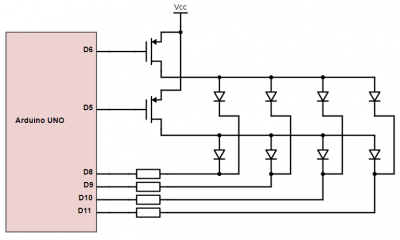
If you want LED to be brighter, then considering a mosfet or a transistor (high-side switch pnp, p-channel…) for each row and a current limiter resistor for each column if you are doing row scanning. People usually do row scanning rather than column scanning.
In case you want to use high current LED, you should put mosfet on each column too (low-side switch npn, n channel…). Or you can use something like Darlington transistor array ULN2803 for example.
Note: by putting a transistor there, you effectively add a NOT gate for each output. Then all you need is invert HIGH to LOW and LOW to HIGH in your code.
Again, you will need a buffer of 4bit x 2 = 1byte.
That is the basic of LED scanning method.
So, you have 8×8 LED matrix, how do you use it?
Well, you can use hardware solution like MAX7219 and just use existing library for that. You actually can change brightness for the whole matrix and daisy chain multiple 8×8 matrices. But it is 1bit grayscale and not so good to expand to higher resolution, so yeah…
If you want to drive directly from arduino, you do the same, hook 8 rows to 8 IO pins and 8 columns to another 8 IO pins. You have to put a current limit resistor for each row, and/or mosfet if needed.
A buffer of 8×8bit = 8 bytes is needed.
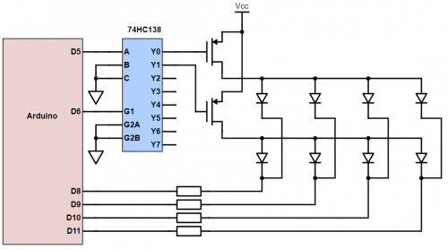
However, Arduino UNO has only 16 available IO pins, which left nothing for button or such. So, we can use 3 to 8 decoder IC to free up some pins.
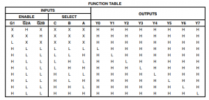
74hc138 truth table
You will use input A, B, C to control output Y0 - Y7 for each row. Let say D3, D4, D5 hooked to input A, B, C for select one of 8 rows and D8 - D13, A0, A1 to control 8 columns. That is you save 4 pins on selecting row.
To free up more pins or, more importantly, expand the LED matrix to 16 or 64 columns or much more than that, you have to replace parallel connection with serial connection by using shift register IC, unless you have luxury of 64 spare pins to use.
For a panel 32×16, you will see pin A, B, C, D for selecting row, which means 2^4 = 16 and hence the term 16s scan rate or 1/16 scan rate. Similarly, for panels with 1/8 scan rate you will see only A, B, C and for 1/32 panels there will be A, B, C, D, E
You can bitbang the output data to shift register like this example below for 32×16 panel
// 32 width x 16 height
// 32x16 bits = 4x16 bytes  = 64 bytes
// for ESP8266
#define MAX_ROW 16
#define ROW_REFRESH_TIME 2 //2ms

#define a_pin 4
#define b_pin 5
#define c_pin 6
#define d_pin 7
#define oe_pin 8
#define stb_pin 9
#define clk_pin 10
#define data_pin 11

unsigned long lastScan;
uint8_t display_buffer [64]; // pixel data for the whole display
uint8_t scanning_row;

void scan_row()
{
  //each byte in one row
  for (uint8_t byte_in_row = 0; byte_in_row < 4 ; byte_in_row++)
  {
    uint8_t pixel_index = scanning_row * 4 + byte_in_row;

    // copy byte data, reverse if needed
    uint8_t pixels_data = display_buffer[pixel_index];

    // bitbang each byte
    for (uint8_t bit = 0; bit < 8; bit++)
    {
      digitalWrite(clk_pin, LOW);
      digitalWrite(data_pin, pixels_data & (0b10000000 >> bit));
      digitalWrite(clk_pin, HIGH);
    }
  }

  // disable display
  digitalWrite(oe_pin, HIGH);

  // select row
  digitalWrite(a_pin, (scanning_row & 0b00000001));
  digitalWrite(b_pin, (scanning_row & 0b00000010));
  digitalWrite(c_pin, (scanning_row & 0b00000100));
  digitalWrite(d_pin, (scanning_row & 0b00001000));

  // latch data
  digitalWrite(stb_pin, LOW);
  digitalWrite(stb_pin, HIGH);
  digitalWrite(stb_pin, LOW);

  // enable display
  digitalWrite(oe_pin, LOW);

  scanning_row++;
  if (scanning_row>= MAX_ROW) scanning_row= 0;
}

ISR(TIMER2_OVF_vect){
  // check if ROW_REFRESH_TIME has passed
  if (millis() - lastScan >= ROW_REFRESH_TIME)
  {
    scan_row(); // update row
    lastScan = millis();
  }
}

void setup() {
  pinMode(a_pin, OUTPUT);
  pinMode(b_pin, OUTPUT);
  pinMode(c_pin, OUTPUT);
  pinMode(d_pin, OUTPUT);
  pinMode(stb_pin, OUTPUT);
  pinMode(oe_pin, OUTPUT);
  pinMode(data_pin, OUTPUT);
  pinMode(clk_pin, OUTPUT);

  TIMSK2 = (TIMSK2 & 0b11111110) | 0b00000001; // set only TOIE bit for overflow vector
  TCCR2A = (TCCR2A & 0b11111100) | 0b00000011; // set WGM00, WGM01 to 1 for fast PWM instead of phase-correct PWM by default
  TCCR2A = (TCCR2A & 0b11110111) | 0b00000000; // set WGM02 to 0 for fast PWM without reseting TCNT2 when it matchs OCR2A
  TCCR2B = (TCCR2B & 0b11111000) | 0b00000100; // 3bit CS2 = 100, which is divisor 64

  // ISR(TIMER2_OVF_vect) will run every 1ms
}

void loop() {
  // do things to display_buffer[] here
}
The code is the same as before, with some modification of function scan_row() to light up a single row. But for 16 rows, you need to run scan_row every 2.6ms, let say 2ms for this matter.
Yes, you can use hardware SPI to to send data instead of bit-banging it for much higher speed.
A buffer of 64 bytes is needed for this panel.
This guy made a video on how to send data to 74hc595 https://www.youtube. … /watch?v=K88pgWhEb1M. It was actually about using EEPROM in an interesting way, but there was also good info on shifting data to a bunch of 595s too.
How’s about the brightness of individual LED?
At this point, you know how to control single-color LED matrix by turning on/off individual LED. But to make it dimly you need to use PWM.
Let assume, you want 24bit RGB color which gives a single color 8bit grayscale or 256 level of brightness on 1/16 scan rate panel. While doing PWM, you need to check each pixel for color over PWM counter and refresh the whole screen for each time PWM counter increases. And thus you have to refresh each row at 256 * 24 frames * 16 rows, in other words, you are able to do 162.7 pixel with clock speed of 16MHz, assuming it takes only 1 single clock for for each pixel over hardware SPI at highest speed possible, 16Mhz. But MCU would have to spend many many clock cycles for calculating, mem reading, register writing… so that it may be able to drive 81 leds on each row smoothly. But yeah, that is for A SINGLE color. For RGB, it would be about 27 leds for each row or total of 432 RGB leds and the MCU is doing full-time job just to drive 432 leds. In reality, you may do 16×16 true color on Arduino UNO, but still it is really tight job.
For 432 RGB leds, you need 3 bytes for each pixel, that is 1,296 Bytes for just screen buffer.
For larger panel such as 64×32 RGB, it is impossible to do 24 frame/s, not to mention you need 6144 Bytes just for screen buffer. Arduino UNO only has 2k of memory, oops!
Of course you can reduce to 4 bit greyscale and use 4 bit PWM which reduce a huge amount of CPU power then maybe you can drive 32×32 RGB led panel, but basically with panel larger than 32×16, you should use faster MCU which also has larger memory.
There is an alternative to PWM, which is Binary Code Modulation. There’s a good article about BCM http://www.batsocks. … readme/art_bcm_3.htm
How’s about dual color panel or RGB panel?
Most of dual color panels are simply made by 2 single color panels in daisy chain. Not really but quite close. A 32×16 R/G panel is pretty much the same as one 64×16 Red panel. Similar thing with RGB panels. This yields the buffer size to 1024 bytes for R/G panel and 1.5kb for RGB panel. You also need to send more data in about the same time frame in order to keep the frame rate high enough.
For anything larger than 32×16 panel, you will need better MCU, STM32F4 or ESP32 for good example in low cost range. Other faster MCU would work just fine but much more expensive.
Existing solutions?
- This guy successfully drives 96×32 RGB panel using STM32F4 discovery board https://fw.hardijzer.nl/?p=223
- You can also use Single Board Computer - Beaglebone Black to do this job https://bikerglen.com/projects/lighting/led-panel-1up/
- Or use relatively cheap ESP8266 dev board such as NodeMCU to drive RGB LED panels (HUB75 connection) https://github.com/2dom/PxMatrix
- This guy, http://openhardware.ro/mymatrix/, wrote a working arduino library for 32×16 red/green panel. The panel has 2 separate data inputs for Red and Green that must be sent data synchronously.
Edit - 10th Sep 2019
I had a project that use a P5 64×32 RGB panel and used PxMatrix to control the LED matrix. So I designed a custom board for it, much less hassle with wiring than using boards like Wemos or NodeMCU.
Just solder a ribbon cable connect DOUT to the esp32 board. Alternatively, use female-female 20cm dupont rainbow color cable for the job. It was a private project and you probably don’t need that extra function on the board so I made a generic version. With this, and probably an ESP32 development board, you can upload code automatically without hassle of holding BOOT button or hitting reset, just like a proper development board.
Here is the pcb for sprintlayout6 and gerber files for pcb service.
[attach=downloads/esp32_pxmatrix_pcb_ledpanel.zip]esp32_pxmatrix_pcb_ledpanel.zip[/attach]
If you need more info on using this board for your project, send me an email [gtext]ceezblog@gmail.com[/gtext]

