Watercooling system on your desktop PC is kind of look cool. But of course, it concerns a lot of precautions.
Water tight
First of all, make sure it is water tight, meaning no leaking at all. You never know if your watercooling is leaking. It happened to me, twice, in the past about 14 years ago. You know, water and electricity they don’t like each other. A few drops of water on motherboard or video card could result in tragedy.
The picture on the left is just click-bait. It’s not mine, it’s from Thermaltake advertisement
Water flow
Somehow water stops flowing, meaning your CPU or GPU is getting hot real quick. Of course not enough to boil water in the tubing but when it hot enough, the tube becomes soft and may come loose and cause leakage. Another possible problem is your tubing is too soft which could folded and cause a clog or restrict the water flow. Or air bubble is trapped in the pump and thus water stops coming out of the pump. Either of that the result is inefficient watercooling system. Oh, did I mention that I used submersible 220v AC aquarium pump and it failed three times. The last time, the epoxy seal on the pump failed and water went into the pump which connected main 220v AC to the water. I literally got zapped when I touched the radiator to check the temperature. I didn’t understand how my computer survived that and still don’t.
After that I ditched my home made watercooling, bought a fancy Coolermaster CPU fan and never look back until last year. It was too hot in the summer so that I usually got huge lag spikes when playing games. So again, watercooling it is.
Early warning mechanism
Well, It is hard to detect water leak even if your watercooling system is just one CPU block (include pump) and a radiator. Mine includes a VGA block. You just can’t install a moisture sensor to detect a leak. But you can detect the water flow.
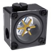
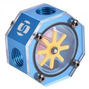
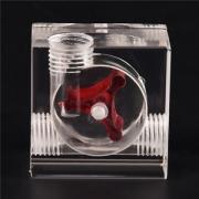
I am not talking about the fancy flow indicators which is just visually indication! Maybe a little.
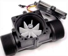
I am talking about the real water flow meter, the sensor stuff that could connect to PC or arduino
If your computer complained on the stoppage of water flow, you would take a look and could fix the problem in time before it was too late. This is the project that I wanted to do long time ago.
Measuring water flow
I can think of 2 possible ways to measure water flow:
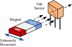
- + Hall effect sensor, like most of water flower meter
- + IR tachometer, like a laser tachometer
Hall sensor and Arduino
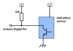
Hall effect sensor is quite promising, except for tiny magnet to work, it must come really close to the sensor to register a pulse. It is the same thing as reading RPM from a PC fan
Take a look here for reading RPM of PC fan http://playground.arduino.cc/Main/ReadingRPM
Easy stuff, just read the time between two pull-down pulses or count how many pulses in a certain time to work out RPM. You can set up interrupt to detect pin change or infinity loop for digitalRead whichever will do just fine since the RPM for the water flow is very low. In my case (12mm tubing with 10mm inside diameter) it is about 100 RPM compare to the conventional 120mm fan of 2700 RPM. Well, it is too low and some PC motherboards won’t register RPM that low.
This method could be achieved by modifying a fancy flow indicator like above and stick a magnet to its impeller and stick a hall sensor to the acrylic window. It would work the same way as commercial products. There is a slight problem: is the magnet corrosive? is the magnet still strong enough through a thick acrylic window? They have the lid of the flow indicator custom made so that the magnet will be very close to the sensor in these commercial products. Well, it’s kinda stuck here.
IR tachometer and Arduino
Like a laser tachometer, I could use the impeller to block the light or reflect the light to the sensor.
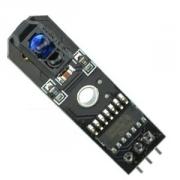
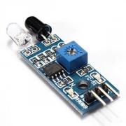
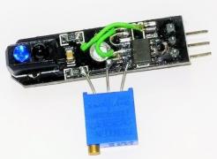
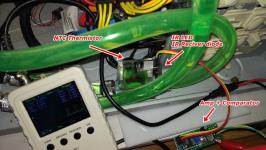
The IR sensors, line tracking / obstacle, were used in experiment.
The left one uses hex inverter IC as a buffer for the signal from the IR detector diode. The right one uses lm393 comparator with a pot for adjusting vref.
Looking on the internet about IR and acrylic or flexiglass, I found out that most of the flexiglass transparent to IR. So this is possible. After a few tries, I gave up on those sensors. None of it worked. They didn’t react to the water flow indicator I have.
It was like the flow indicator is totally transparent to the sensors. When I put the sensor against a solid object, ie: my computer case, it worked just fine. I was missing something here. Oh, the water absorbs IR light and the acrylic reflect very little IR light so that there was no IR light reflect back to the IR receiver diode, snap!
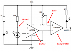
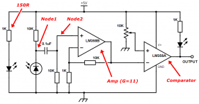
Ok, ok, there must be some light reflect back. Maybe it was too weak for the hex inverter to register a LOW level and also too weak for the LM393 comparator. Turn out I was right. The voltage at Node1 in the modified circuit below was too weak. Result on oscilloscope showed a faint signal of 0.2 Vp-p compare to a fully-swing output of ~4.3 Vp-p from LM358. No wonder I got nothing from the original circuit.
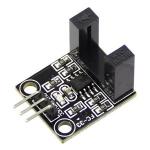
I had to put vref to ~4.8v to get it work, but still it wasn’t stable nor reliable. Anyway, it was too hard to get good position for the sensor to read reflect IR light from the impeller. So I designed a custom IR sensor like this one below but bigger.
Custom IR tachometer
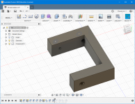
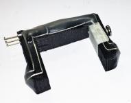
I copied the design of an IR end-stop sensor to put the emitter IR led and IR photodiode facing eachother. The *frame* of the sensor is 3d-printed and meets thickness of my water flow indicator with a screw to secure the sensor. I also built an amplifier circuit using LM358 to amplify the signal from the photodiode.
I had to change the current limit resistor for the IR LED to 120R (~35mA) to increase amount of light for stability, that’s because of the water (or coolant) absorbs quite great deal of IR light. The buffer was replaced with a non-inverting amp included a passive high-pass filter which cut off DC voltage at Node1. The signal at Node2 will be amplified 11 times and probably gives output in range 0v and 4.3v. The minimum and maximum value doesn’t matter for there is a comparator with adjustable vref. It worked more reliable and I got nice output of pulses.
IR tachometer and Arduino code
Just like reading RPM from PC fan, we can use INT (interrupt) or PCINT (pin change interrupt - I prefer port change interrupt). Things getting complicate with INT and PCINT.
Well, there are 2 INT (INT0, INT1) on D2, D3, but we have 3 ports (PortB, PortC, PortD) for PCINT which cover all pins on Arduino Uno or similar (atmega328). We can put 2 functions (ISR - interrupt service routine) for each INT0, INT1 that can trigger only on specific event: RISE, FALL, CHANGE. In other hand, we have 3 functions for 3 port change interrupt. Any change on a port will trigger the correct Port Change ISR and we have to figure out which pin in that port is changing and it is rising or falling.
If reading RPM from the IR tachometer sensor is the only thing arduino will do then we just use an INT pin such as D2 and all. But we often have more sensors or devices: more PC fans, a LCD screen maybe or PWM controlling circuit for the fans. We really can’t do infinity loop just doing digitalRead on a pin to get the time between 2 pulses. So, PCINT it is.
There are a few library for INT and PCINT you can use: NicoHood PCINT library, GreyGnome EnableInterrupt library. They are well documented and simple to use. So I just pick the library with simple example, NicoHood’s one.
The code:
#include "PinChangeInterrupt.h"

// define PCINT pin for the signal from tachometer
#define TACHY_SENSOR A3

// for counting time between pulses
unsigned long Tachy_count;
unsigned long start_counting_time;
unsigned long end_counting_time;
bool Tachy_counting;

void setup() {
  Serial.begin(9600);

  // PULLUP is not neccessary for my tachometer sensor
  // but for it to work with PC fans with hall sensor
  pinMode(TACHY_SENSOR, INPUT_PULLUP);

  // Attach the new PinChangeInterrupt
  attachPCINT(digitalPinToPCINT(TACHY_SENSOR), TACHY_ISR, CHANGE);
}

// +----+           +----+           +-----
// |    |           |    |           |
// |    |           |    |           |
// +    +-----------+    +-----------+
// 1    2           3    4           5 .....

// counting time between beginning of 2 pulses, increase this for more accuracy
#define PULSE_LEN 3 // 1 pulse, from point 1 to point 3
//#define PULSE_LEN 5 // 2 pulses, from point 1 to point 5
//#define PULSE_LEN 7 // 3 pulses, from point 1 to point 9
//#define PULSE_LEN 9 // 4 pulses
//#define PULSE_LEN (n*2 + 1) // n pulses

void TACHY_ISR(void) {
  if (!Tachy_counting) return; // if not measuring

  if (Tachy_count==0) start_counting_time = micros();

  if (Tachy_count >= PULSE_LEN) // after some pulses
  {
    Tachy_counting = false;
    end_counting_time = micros();
    Tachy_count =0;
    return;
  }

  Tachy_count++;
}

unsigned long Read_tachy()
{
  Tachy_count =0;
  Tachy_counting = true;

  // waiting for result or doing something else instead
  // result will be available when Tachy_counting == false
  while (Tachy_counting) delay(1);
  unsigned long periods = end_counting_time - start_counting_time;

  // f= 1/T (Hz) ; T= t/n; n= (PULSE_LEN-1)/2; f= 1/(t/n) = n/t ;  v = f * 60 (RPM)
  // Hence, f = n*10^6 / t (Hz) or v = (PULSE_LEN-1)/2 * 10^6 * 60 / t (RPM)
  //  v = (PULSE_LEN-1) * 30 * 10^6 / t (RPM)
  return (unsigned long) (PULSE_LEN-1) * 30000000 / periods;
}

void loop() {
  Serial.print("RPM : ");
  Serial.println(Read_tachy());
  delay(1000);
}
So yeah, write a PC program to connect to arduino and read RPM and popup warning is kinda cool, maybe for another sunny day.
[tag]IR tachometer, water flow meter[/tag]

