I always want one since it first appeared on the interweb around 2005. The very first version used PIC chip and it originated namely LC meter. I actually bought all components but at that time, I had no clue how to program PIC, and thus I failed to build one. I still have no idea how to program PIC chip until now :D
Chinese clones
I was a little bit lazy :P, didn’t make a custom pcb myself but bought a clone from ebay. It is open project on the internet which you can found a huge discussion thread about these Chinese clones or the original one on mikrocontroller.net and source code svn, github.
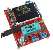
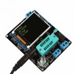
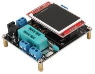
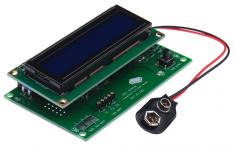
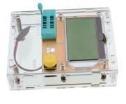
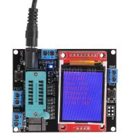
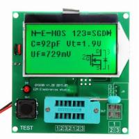
Apparently, those Chinese manufactures just copy the circuit, make a good looking pcb and just slam the pre-built firmware from the internet on it without modification of a single line in source code. That’s why some of them look kinda suck like these:
The first one using st7735 with 4-line GUI and pretty much waste half of the screen, while the second rotated 90 degree which you can fix it by uncomment a single line code and rebuild the firmware.
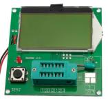
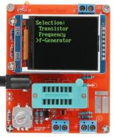
I believe the author(s) build the firmware for 4 line character LCD and upgrading overtime to support color graphic LCD which has twice in resolution. Re-write the whole GUI section would take a lot of work and thus more likely a separate project. Anyway, their works look really nice on the right LCD
Hardware fix
My transistor tester has the same LCD controller as my very first TFT screen I own, ST7735. I took a peek in the code and found out that it uses software spi which is 8 times slower than hardware spi as my previous experience. Quite slow, but acceptable. There is not much I can do actually. So I decided to give 16Mhz xtal a go but the board just showed welcome screen, flickering then white screen.
After taking some measurement, I found out that the Regulator marked 7550 (it is HT7550) went nut and output 6v on the chip m328p. What the heck?! How could a simple changing xtal can affect regulator??? But switched back to 8MHz, it worked like nothing happened. I have no idea how could it be possible.
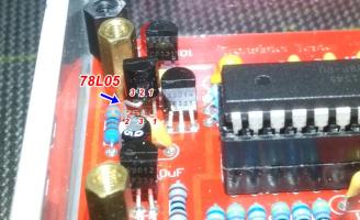
I didn’t have any pin compatible to regulator 7550, but I have some 78L05s. OK, if I cannot change the rule, I bend the rule :D. So I bend the middle leg of 78L05 to the side and soldered to the board in place of 7550. Looks odd but works :D. Vcc on m328p now shows 4.95v and now LCD draws 2 times faster.
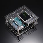
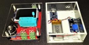
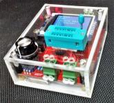
I can’t leave this *toy* naked like this, so I bought an acrylic case for it. Unfortunately, the seller sent me the wrong one. I don’t like that shell case anyway. So I made my own shell case using 3mm acrylic sheet, not so pretty as the acrylic glue sticks all over the corners and edges.
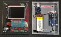
Of course a rectangular 9v battery (standard PP3 type) won’t fit in the small case I made, that is why I use a Lithium ion 3.7v for the power supply which sit in my component bin for months. Also a charger board and DC booster will do, especially easy charging with micro USB port. Anyway I need to protect the battery from the pointy solder joints on the back of PCB and a sheet of PVC cut out of a milk bottle should do the trick.
I added an slide switch (not in photo) to prevent current leak from the DC booster module. After all, it is just 3.7v 430mah battery which waste around 30% energy to boost to 9v. The li-ion charger board has over current and low voltage protection so that the the battery won’t over discharge. I have been using it for a week now, and battery still doesn’t need recharged yet.
Warning!!!
you don’t want to poke a hole on Lithium-ion battery while put it in a case underneath the board, it could explode!!! Search youtube video about “lithium ion battery explosion”.
Firmware modification
As mentioned above, that clone has bad user interface and needed to be improved.
There are 2 branch of firmware: M (Markus) and K (Karl-Heinz) as they have slightly different in function. Mine came with K firmware. Unfortunately there are almost a hundred of source code files, and I couldn’t make head or tail out of it.
Thus, I used M firmware. Installed cygwin to get make utility and use AVR compiler that comes with Arduino IDE then I am able to compile the source now but port it to arduino project is out of the question, too much works to be done…
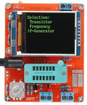
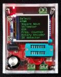
It comes with many functions in the menu:
[INDENT]PWM
Square wave
Voltmeter
Capacitor ESR
Frequency Counter
Rotary Encoder
IR detector
Opto Coupler[/INDENT]
And yes, it can detect resistor, inductor, capacitor, BJT, FET, even SCR (I think).
[attach=download/avr-ttester1.26c.rar]avr-ttester1.26c.rar[/attach]
Now I am happy with it. Thanks Markus and Karl for wonderful job!
