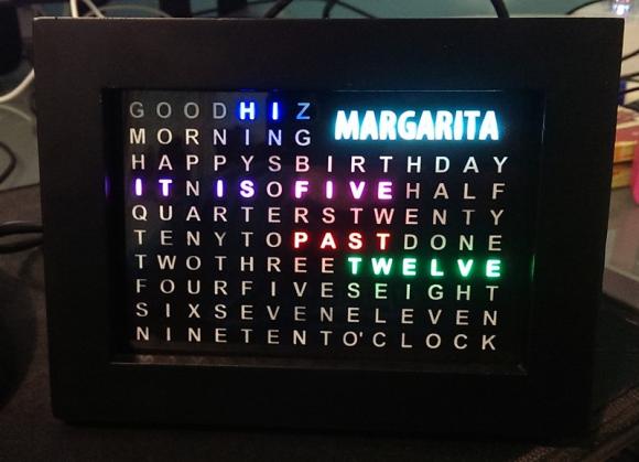
I wanted to make one a few years ago but I didn’t have much time as well as I didn’t know how to do it, or was too lazy to do it :D
Back then, I lacked of enthusiasm, motive and didn’t want to learn new things. Until this year, I had more free time and change of mind, I want to learn new things. So, I started this project, a few years after
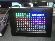
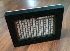
WordClock in action
Part list
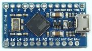
- Uno / Leonardo / Pro Micro / Teensy2.0 (anything with mega328 or mega32u4)
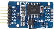
- DS3231 - Extreme accurate RTC module
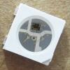
- WS2811B - Addressable RGB LED
- Small Photo frame 15.5×11.5cm from ebay
- 3mm MDF sheet (about 16×12cm)
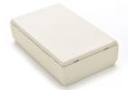
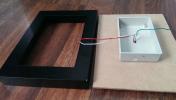
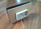
- Small plastic box 8×5x2cm from ebay
- A4 Clear Label sheet + Laser printer / decal cutting to make stencil
- Photoresistor - LDR
- 0.1 uF ceramic caps (SMD 0805)
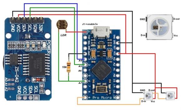
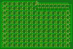
The circuit
The Hardware
As part list suggests, you can pretty much use any development board, as long as the MCU has at least 15KB Flash and 1.4KB RAM. Of course you can tweak the code to use less RAM and more Flash or cut off some extra functions to reduce a few kilobytes. Now think about it, it may fit into the mighty Tiny85!
Anyway, narrow down to mega328 and mega32u4, I chose ATMega32U4 since it has build-in USB connectivity for ease of mind and thus no need for hardware serial adaptor and any ATMega32U4 developing board would be fine. I heard from the internet, Sparkfun Pro Micro has different bootloader and different VID, not the generic one like Arduino Leonardo, so there might be some hiccup along the way with driver detection if you use it as the brain of this project. However, you can flash Leonardo bootloader and it will be just fine.
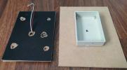
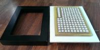
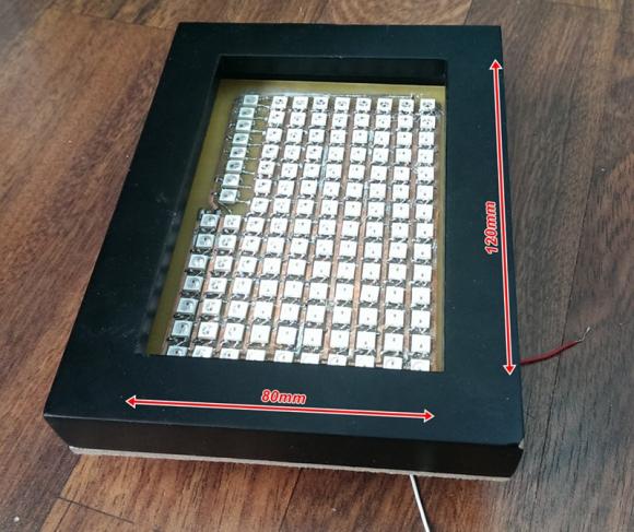
Next thing should be considered is the chassis or the frame. I chose a small photo frame. I designed the clock face that fit the frame and also the pcb art work. Well, soldering 134 pieces of 5050 LEDs on a small area like that is sure time consuming.
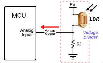
Oh, when lights are out, wordclock becomes so bright that could make you eyes uncomfortable. So we need a dimmer function using LDR (Light-dependent Resistor, it reduces resistance when exposed to light).
Input pin on MCU must be an Analog input so we can read voltage output from voltage divider. So, get the threshold value when the room is almost completely dark so wordclock should reduce brightness when input is below threshold value. Your threshold value might be different, depends on value of LDR and how much it drops its resistance when exposed to light.
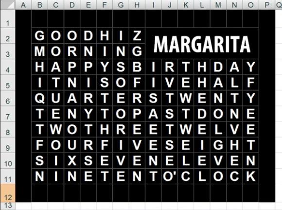
Another important thing is the stencil for the clock face. If you have access to a decal cutting service, good for you. If you don’t or the price of vinyl cutting service is too expensive, you can use the alternative way to make stencil, that is you need clear A4 label and a laser printer. Yes, print negative image of the clock face and stack up 3 identical layers and you will have a nice stencil which blocks most of light.
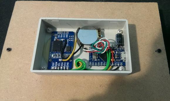
Then the next step is put everything together. And also put a 1000uF cap on 5v and GND to prevent voltage dropping when 134 LEDs light up at one time (mostly start up time).
Software
At first, testing a single WS2811B LED with Arduino using NeoPixel library sample with one WS2811B LED. Then hooked up another WS2811B LED to the chain and try different color on both LEDs, and then move to the whole LED board to see if it could do. Well, turned out a few 80th-ish LEDs didn’t work. I had to take it out and put another one in. After replacing 4-5 LEDs, I experienced the same thing, then I realized I didn’t put filter caps to stabilize voltage for these LEDs. So I put on each row two 0.1 caps and it worked perfectly.
OK, next thing to do is add clock function, take from previous project of mine.
Files
[attach=download/WordClock.zip]WordClock.zip[/attach] - pcb file (sprint layout 6) and source code for Arduino IDE
[attach=download/DS3232RTC.zip]DS3232RTC.zip[/attach] - use for DS323x and DS1703
[attach=download/arduino-lib-Time.rar]arduino-lib-Time.rar[/attach] - legacy time library
Other notes:
- From update Arduino 1.6.12, they adopted new time library and thus the old time library becomes legacy. But DS1703RTC lib or DS3231RTC lib still use the *legacy* time library. If you get error with tmElements_t, just rename hardware/tools/avr/avr/include/time.h to anything like time_new.h
- You can use WS2811B strip instead of making a PCB for the LEDs. Then you have to use bigger photo frame or a custom shadow box for the job. But if it’s bigger than A4 paper, you have to find another way for the stencil and you should make light dwell as well or else light from this *pixel* will bleed to surrounding *pixels*, like a cheap backlit keyboard.
- Or use normal LEDs and with two 4-16 decoder to control LED matrix. Or use Arduino Mega which has plenty of IO pins to directly drive LED using IO pins. But for these solutions, you can’t change the *pixel* color, yes?
- Recently I have some experience with ARM - STM32 microcontroller, good price, good features, higher speed (72Mhz), has more IO-pins, and the most important thing is it is *somewhat* Arduino compatible. So, pretty much with little of modification, the code for atmega32u4 will work for stm32
[tag]Arduino, WS2811B, Word Clock[/tag]
