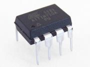
Sometime, you need a small circuit to flash some LEDs or do some simple task, say, power on delay function for your DIY amplifier, power on reminder for your soldering station (beep every 3 mins) - which I forgot to turn off all the time… probably, an Attiny13 is just what you need.
Sure, it’s nicely done with a 555 timer although it comes with some drawbacks: the output length of pulse is not precise because of % error of components, or it requires a few more extra components than an attiny13 solution.
Since I can get 10 of these little chips for around AU$6 on ebay, so cheap that make the price gap of 555 and tiny13 doesn’t matter anymore. So I started to replace 555 with Attiny13.
Anyway, Attiny13 is a microcontroller which you need to program in order to work.
Programing is easy, even easier if using Arduino IDE.
You’ll need:
- + ISP Programmer - USBtinyISP is my favourite, an Arduino will do just fine
- + Arduino IDE 1.6.9 (up to this post), version 1.6.12 works fine too
- + Core13 library from smeezekitty - download link, support link
- + HV Rescue Shield / Attiny fusebit doctor (Optional)
Using DIP chip, you can program it on bread board easily, but it is quite difficult to program SMD chip without soldering on to a pcb.
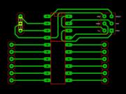
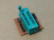
I happen to have a spare 20-pin Zif socket laying around
So, How to do it?
Step 1: Download the hardware configuration for Tiny13 at sourceforge - smeezekitty. You can download from my blog - [attach=download/core13]core13.zip[/attach] for Arduino 1.6.9 or higher. I took the work from smeezkitty and fix the boards so that it works flawlessly with arduino IDE.
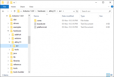
Step 2: Extract and copy the content to folder …/arduino/hardware/ and you will have a folder structure like this
Step 3: Start Arduino IDE and see if errors show up
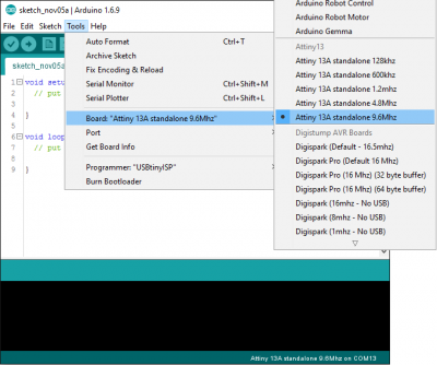
Step 4: Choose the right board Attiny 13 with desired speed
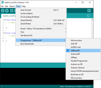
Step 5: Choose USBTinyISP as programmer. If you use ArduinoISP, first upload sketch turns UNO into ISP programmer and then use it to program other boards.
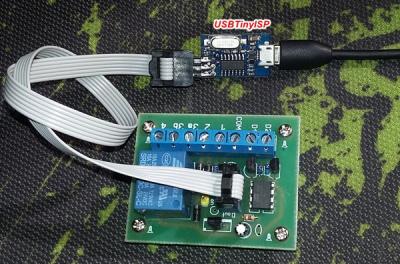
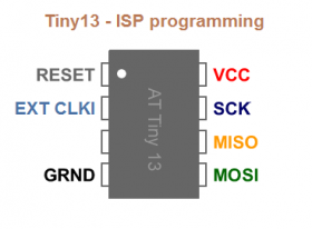
Step 6: Connect ISP cable to the tiny chip, using breadboard or an ZIF adapter, or plug in directly to your project board
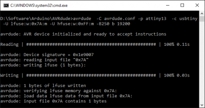
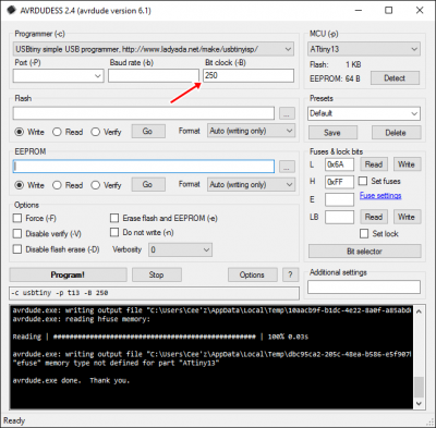
Step 7: Burn bootloader, actually it sets fuse to run at desired speed. If you use the modification version from my blog, it should set fuse alright. If not, you have to use avrdude or even better one, avrdudess to set fuse:
Step 8: Write some sketch like blinking a LED
[INDENT]
// The Classic sketch: HELLO WORLD
void setup() {
  pinMode(1, OUTPUT);
}

void loop() {
  digitalWrite(1, HIGH);
  delay(1000);
  digitalWrite(1, LOW);
  delay(1000);
}
[/INDENT]
Step 9: Press upload to compile and upload the sketch.
That was easy!! :D
List functions that Core13 support:
map()
random()
randomSeed()
millis()
micros()
delay()
delayMicroseconds() *
analogRead()
analogWrite()
pinMode()
digitalRead()
digitalWrite()
pulseIn() (Untested)
shiftIn() (Untested)
shiftOut() (Untested)
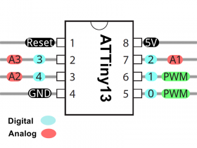
Pin map for Arduino IDE
This project is a sub project of this project: game show buzzer system
[tag]Arduino, aTTiny13 programming[/tag]
