It is sometime called game show buzzer lockout system, but I thought many people confuse with the name so I changed it.
If you’ve watched some game shows like Family Feud, you probably know what a game show buzzer is. And yes, it is a set of buzzers that once a button is pressed, the other button is deactivated to indicate the player who takes answer fastest. It usually is 2 or 3 players at a time on TV. That is easy. But what if you need a buzzer set for 10+ players or teams at the same time. Well, not easy anymore.
I had a project like this about 7 years ago, using an 89s52 as the brain of the system. I just ran the infinite loop to check for some digital pins if connect to ground then turn on a specific the light. I thought it worked not really well since 89s52 run at 20Mhz, not fast enough. I mean the little MCU have to check for 10 digital pins, it should take some time to cycle the checking loop. So, if 2-3 players press the button in that very short time, it doesn’t matter which player press first, but the digital pin in first order always get a lock on the buzzer. In other words, theoretically the first player on the list usually get a lock on the buzzer. So, it’s not really fair. Nobody recognized that anyway. And the wiring also was horrible as well, it looked like a big mess.
Recently, I had this project for a group of youth people. They need 12 stations for 12 players at a time.
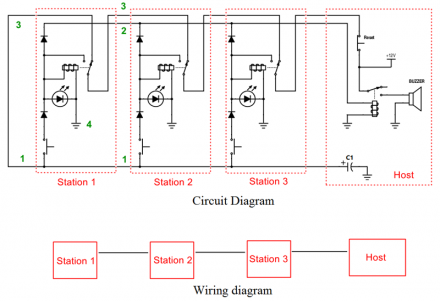
I chose a different circuit this time. Found a very interesting circuit on the net, it uses 4 wires to connect each station in serial instead of my old method: all stations have to connect to host - which the host must have as many digital pins as how many stations are in used, and so are the wires.
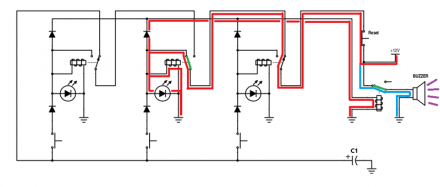
The circuit
As you can see in the schema, this circuit has the potential to expand to more stations , say, 20, 30 or even more. Haven’t try that much, but the first prototype I built works fine with 12 stations without any glitch.
This is just the basic circuit to show how it works. You have to work out a little from this circuit to make it works in real circuit.
How it works
It is quite simple.
[INDENT]Ready state:[/INDENT]
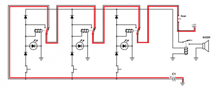
- • At first, all relay in the stations are in OFF state. The current from 12v source will travel in the circuit as the red line which eventually charges up C1
[INDENT]Transition state:[/INDENT]
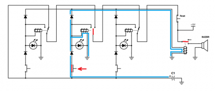
- • When a button Btn2 on station 2 is pressed, for example, the relay of this station is now powered by 12v source to initialize switching the latch.
- • As soon as the latch disconnected from normally close position, N/C, it cuts off 12v source that charging C1. Thus the entire circuit is powered by C1 as the blue line.
- • RL2 is now powered only by C1 until the latch reaches normally open position - N/O. It doesn’t require much energy to finish swinging the latch now as most energy needed to init the swing of the latch was provided by 12v source.
[INDENT]Locking state:[/INDENT]
- • The relay finishes switching, COM and N/O are connected thus the coil of RL2 is now powered by 12v source, and it stops using energy from C1, since voltage from C1 is about 11.3v (12v minus 0.7v - forward voltage of diode). Also this 12v source is not charging up C1 thanks to the diode in serial with the button Btn2.
- • If another button on other station is pressed, e.g. Btn3, the coil of that relay RL3 will be powered by C1. Fortunately, there is not much energy left in C1, not enough make the latch of RL3 move.
- • Same thing happens to other stations, as C1 has energy no more to power up RL1, RL3, RL4, RL5… to make change to the circuit. So, all stations are completely locked in OFF state leave only station 2 locked in ON state.
Note on design - mostly on Transition state
The clever of this circuit is the two Diodes on each station that block 12v DC from charging C1 and also block 12v goes from ON station to OFF station, and C1 stores just enough power to turn only 1 relay.
For small value of C1, smaller than 10uF, it doesn’t have enough energy for relay to completely turn the latch, like just half way and out of energy then the latch swings by the spring. Hence, it make repeat clicking sound of the moving latch.
If a much larger cap like is used, there is plenty of juice in C1 to power up another relay after a relay finish latching. So if another player on the upper chain press his button and activate relay, this relay will cut off power of the previous player and change lock. I call this unstable locking state and is what I don’t want.
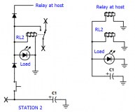
C1 also powers a load on player circuit. It could be a simple LED, a light bulb or a small circuit of 555 timer to do thing like flashing a LED stripe in specific pattern. Thus the circuit will look like this:
After trials and errors, 47uF is quite OK for my type of relay, 12v Relay with coil resistance about 400 Ohms (~30mA needed) and the load is a small circuit of Tiny13 which works after some warm up time (acts as delay). Tiny13 circuit starts consuming considerably energy only after relay finish turning, so it can be omitted from equation.
As I make some trials and success with C1 = 47uF, I assume 22uF is good enough for a single relay which need ~30mA.
If you use a heavy load like 12v 10w light bulb. Say 12v 10w light bulb will consume 1A. Additionally, 2 relay (1 from player circuit, 1 from host) will take another 60mA make it totally 1060mA. Thus C1 should be 22*1060/30=777.33uF. So, you could try closest value of C1 680uF and 1000uF to see if it works. This’s just roughly calculation and it is not correct as you may need to use much bigger cap for C1 such as 4700uF or larger.
you can replace that simple load with a relay to make it simpler. Assuming all the relays are the same type and thus it would take the same time to switch from N/C to N/O. By the time your load starts taking current, the circuit is in in locking state already, and your load is powered by 12v source now. Thus, C1 should be 22uF*3 = 66uF or use 100uF would be OK.
Recently I have some relay demands higher energy than what I had before. That new relay won’t make it to locking state but makes clipping sound like a motor with low ratio gearbox while the old ones still works fine with 47uF C1. I have to replace C1 with 330uF. It still works OK after that.
Prototype
- Use Tiny13 circuit which flashs a short LED strip as load
- Reset button is replaced with a tiny13 circuit in order to auto cut off power after 5s
- Use an atmega328 as music player to play sound effects
This schema is for the prototype
And some photos
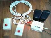
The box of stations are made of white translucent flexiglass (opal color) which is lazer-cut and glued together thanks to a friend of mine. And LED stripe is put inside the box so that when it is in lock state, LED stripe will light up the box.
[attach=downloads/buzzer.rar]buzzer.rar[/attach]
Include:
- PCB file for sprint layout 6
- schema file splan
- Arduino sketches for Host, Station and wav-player
Make Changes
My original plan is to use a sound module like wt588d-16p. It was easier this way but when I tested it using Uno with 12v adaptor, the regulator on Uno fails and shorted 12v ono output that instantly killed atmega328 and the sound module. It was smell really bad.
Tire of waiting for too long for another module from ebay, I decide to use mega328 as a wav-player module using TMRpcm to play sound from micro SD card.
I had some PCBs ready but 3 of them just stop working for a mysterious reason. I think it is bad chips since I just desoldered the atmega328 out and soldered a new atmega328 in and it worked again. Maybe it’s because the price is so cheap, 10x atmega328 smd for AU$17, I couldn’t resist :D. Turn out it was because I missed 10k ohm pull up on reset pin. It makes reset pin voltage float and the chip went crazy after powered on a few minutes.
Version 1.0
Success with prototype, I upgrade to version 1.0 using one single mega328 to handle the timer and wav-player. Also order nice PCB from a professional PCB service.
For this set of buzzers, I put a small speaker and an amplifier inside the host, using an 2×3w rated 5v class D amplifier - PAM8403 for $AU 1 (yes, 1 aud). For power supply for the amp, I connected it to the same 5v supply for the atmega328. It was horrible, heavily noise came out the speaker and the 5v regulator was super hot. So I made another power supply for the amp using the same dirty trick lm7805+heat sink and 1000uF. After that, noise was audible within about half meter away from the small speaker, so it was acceptable.
Maybe it was a mistake using 5v class D amp for the job because I can’t find a decent power supply for the amp. I mean I can’t find a cheap and decent DC-DC step down converter that handle 1amp output nicely. Hence, it would be a lot better if I use 12v class D amp, 2×15w rated PAM8610, so I don’t need to get a proper power supply, instead just a couples of filter caps should do the trick. For the next set of buzzer then :D
[attach=downloads/Buzzer2.rar]buzzer2.rar[/attach]
Include:
- PCB file for sprint layout 6
- Arduino sketches for Host and Station
[tag]Game Show Buzzer Lockout System[/tag]


Wednesday, April 27, 2016 at 01:54:31
thank you very much but i have 1 question if i use lamp 12v ,10w why i press a button lamp not light
at 03:51:24
But only clipping noise comes from relay?
Well, take a look at [B][COLOR=#008040]Transistion state:[/COLOR][/B]
If you replace LED with 10w lamp, it will take most of power from the capacitor C1 (22-47uF) leaving not much for the relay in each station. There won’t be enough energy from C1 for the relay to finish switching the latch.
Here is my calculation: internal resistor of the coil from relay is about 400 Ohms, but 10w lamp is 12^2/10=14.4 Ohms. It can be calculated as simple as parallel circuit between relay coil and lamp. Thus R total = 400 || 14.4 =13.5 Ohms. The current ratio between branch relay coil and branch lamp is about 14.4/13.5 : 400/13.5 = 1:30. Assume that 22uF can store enough energy for 12v relay to finish switching the latch (from my circuit), you will need a capacitor that at least 30 times bigger than 22uF, about 660uF in order to get enough energy for relay to complete switching the latch.
Anyway, I need more information for diagnosis.
PS: Bạn có thể dùng tiếng Việt nếu thấy không thoải mái với tiếng Anh.