For the first time having experience with arduino and TFT screen, a TFT display shield should be better than a breakout TFT display, because a shield is something that made for plug-n-play, like a usb thing, just plug it in the computer and it works right away.
That what I thought when I bought this shield.
But I was wrong.
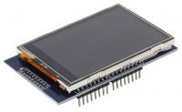
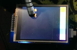
It is the cheap TFT display you will get from ebay. There are serveral models using different drivers - mine uses LGDP4535 - that looks like the picture above.
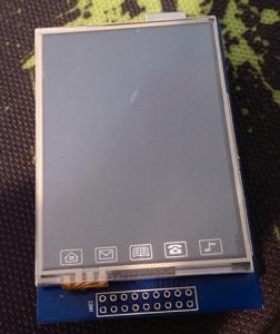
In fact they add some extra features to the one I bought:
It’s really stupid with these Icons. It looks like the touch screen of a cheap-crappy-chinese phone. However, I managed to remove that and leave a clean TFT screen. It is quite easy. The touch screen made of a piece of glass that sticks to the underneath screen using sticky tape instead of bezel frame. Just lift the glass up and it comes out. But one problem: you have to use double side sticky tape to replace the tape you take out. For me, I will use silicon to stick the touch screen to the TFT screen. Mean while, I use clear sticky tape to stick the touchy-glass to the whole thing.
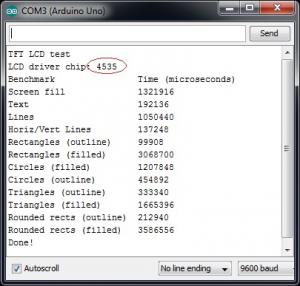
I searched google and tried several libraries and sample codes but non-success, all I could do is get the LCD driver chip id: 0×4535 and a blank white screen until I found a thread on forum.arduino.cc for the same TFT LCD shield brand name www.mcufriend.com.
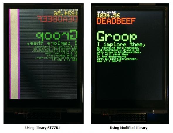
I tried the library for the driver ST7781 from SWTFT and amzingly the screen works, barely :D . The screen is mirror and 1/6 of it on the left side just show rubbish. For the first time, it works, technically, not fully functioning but at least it shows something.
I did more search on the chip 4535 and finally found the datasheet and application note of this chip LGDP4535 from LG! So, I took the Initialization command found on datasheet and put it in the barely-woking library and voila everything becomes perfect.
Other people on arduino have the exactly look alike LCD shield like mine, but it comes with the chip ST7781, ST7783 or HX8347… which someone already wrote libraries for them.
When I try the touch screen, I find out that the default TouchScreen has the Zero point (0,0) located in the bottom-right corner not top-left like the LCD. I added rotation ability to the TouchScreen library and renamed it to zTouchScreen.
Of course, I have to calibrate the limit of the touch screen.
My litmit X,Y look like this
#define TS_MINX 840
#define TS_MINY 820
#define TS_MAXX 120
#define TS_MAXY 160
It looks strange when Max_X is smaller than Min_X. The thing is this helps rotate the screen 180 degree.
At first, I tried some random numbers, uploaded the sketch and tried the touch screen. Did it again until everything seem ok. Well, It’s kinda suck when I have to do it manually.
There are other ways to calibrate this touch-screen like this link or use the sketch at the end of this post. Thanks Nick for the sketch that helps a lot in calibration.
After a while playing with it, I realize this is resistive touch screen, not capacitive touch screen. I can use a pointy stylus to get more accuracy touch point, but it still sucks.
Some people report that touch screen pins are different in their TFT shield
Mine is:
#define YP A1
#define XM A2
#define YM 7
#define XP 6
Others is
#define YP A3
#define XM A2
#define YM 9
#define XP 8
When using zTouchScreen, remember to initialize these variables:
ts.InitVariable(rotate, width, height, TS_MINX, TS_MAXX, TS_MINY, TS_MAXY, MINPRESSURE, MAXPRESSURE);Width and Height are the in the default orientation, for this shield it is rotate = 0 and and width = 240, height = 320. If you want to rotate the screen 90 degree, just put rotate = 1, but width and height still the same (240 and 320).
The last test is displays an 24bit bitmap image using SD lib
[ANCHOR=download]Download
[attach=download/TFT-LGDP4535.rar]TFT-LGDP4535.rar[/attach] - Main library for LGDP4535 - Updated 2015/8/19
[attach=download/Adafruit_GFX.rar]Adafruit_GFX.rar[/attach] - Graphic library for rendering
[attach=download/LGDP4535_datasheet.rar]LGDP4535_datasheet.rar[/attach] - Driver chip LGDP4535 datasheet
[attach=download/zTouchScreen.rar]zTouchScreen.rar[/attach] - Modified TouchScreen Library - Updated 2015/8/5
[attach=download/Arduino-TSCalibration.rar]Arduino-TSCalibration.rar[/attach] sketch that used for touch screen calibration - Thanks Nick
———————————————————–
Update 2015/11/8:
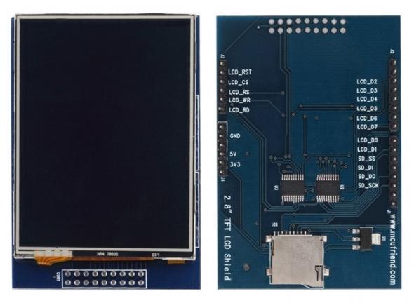
For Arduino Mega user, the SD card is not going to work, because SD card module on this shield is using Hardware SPI
Fortunately, the display still works fine, because this TFT display using 8-bit bus interface (LCD_D0 to LCD_D7) instead of SPI.
So, what can we do?
Luckily, there is solution for this problem by using software SPI
Open this file Arduino/libraries/SD/src/utility/Sd2Card.h
You will see some interesting information from line 34
/**
 * USE_SPI_LIB: if set, use the SPI library bundled with Arduino IDE, otherwise
 * run with a standalone driver for AVR.
 */
#define USE_SPI_LIB
/**
 * Define MEGA_SOFT_SPI non-zero to use software SPI on Mega Arduinos.
 * Pins used are SS 10, MOSI 11, MISO 12, and SCK 13.
 *
 * MEGA_SOFT_SPI allows an unmodified Adafruit GPS Shield to be used
 * on Mega Arduinos.  Software SPI works well with GPS Shield V1.1
 * but many SD cards will fail with GPS Shield V1.0.
 */
#define MEGA_SOFT_SPI 0
So, you need to change it to
/* #define USE_SPI_LIB */    // commented out
#define MEGA_SOFT_SPI 1 // change to 1 from 0
Thanks Tony for this found
[tag]TFT shield LGDP4535[/tag]



Sunday, May 10, 2015 at 22:54:44
Thank you so much for this entry. I have been searching the web for a whole day to get this touchscreen running, edited code and was not abled to get rid of that white stripe on the left side and now it works perfectly because of your help :)
Saturday, May 16, 2015 at 02:25:50
Glad I can help :)
Sunday, May 24, 2015 at 06:37:03
Thank you very much I have the ST7783 version of the same thing and the touchscreen input was exactly backwards, your change to TouchScreen.cpp fixed it! thanks!
at 06:52:56
Now I need to calibrate the limits of the touchscreen, in the post you said it was for another day, will that post be coming anytime soon?
Thanks
at 12:06:52
Found something that removed the requirement for calibration, this may help you too.
This guy says the screen may be rotated 180degrees out of phase with the touchscreen, which is what I experienced.
https://mentaladventuresofnanoborg88.wordpress.com/2014/08/04/finally-got-the-touchscreen-shield-to-work/
“The touch pad was rotated 180 degrees from the display so adding tft.setRotation(2); in the setup before tft.initDisplay(); will line the two up again.”
This fixed it for me.
It would be nice to have some uniformity to setting up these little units, but I got mine barely used for less than $3 USD on ebay, I guess the last owner didn’t want to mess with it. Not bad for the price.
Thanks
Tuesday, May 26, 2015 at 02:17:12
here is how to calibrate the touch screen http://www.seeedstudio.com/wiki/2.8′’_TFT_Touch_Shield_V1.0#How_to_calibrate_the_touch_screen_.3F
Yes, you can rotate the LCD to match the touch screen but I wouldn’t do that. It won’t work in landscape mode and I don’t like the LCD up-side-down to be seen correctly :D
*Rotate* the touchscreen it if you wish, never try it, but it should work
[code]// function to change the *virtual* orientation of the touched point.
TSPoint RotatePoint (TSPoint tsp, int orientation)
{
int x = tsp.x , y = tsp.y;
if (orientation == 1) // 90 degree
{
x=tsp.y;
y=240-tsp.x;
}
if (orientation == 2) // 180 degree
{
x=240-tsp.x;
y=320-tsp.y;
}
if (orientation == 3) // 270 degree
{
x=320-tsp.y;
y=240-tsp.x;
}
return TSPoint(x, y, tsp.z);
}
// —– example —–
void main()
{
// do what you need to do
TSPoint p = ts.getPoint();
// scale from 0->1023 to tft.width
p.x = tft.width()-(map(p.x, TS_MINX, TS_MAXX, tft.width(), 0));
p.y = tft.height()-(map(p.y, TS_MINY, TS_MAXY, tft.height(), 0));
// rotate 270 degree
TSPoint A = RotatePoint (p, 3);
// do something
tft.fillCircle(A.x, A.y, 10, GREEN); // draw a filled circle
[/code]
Sunday, July 12, 2015 at 08:08:17
You are my new god! I have been working for days on finding a library that would bring my LCD display to life. I finally got the chip identified to LGDP4535 and Google led me to you. Now it works perfectly even the reverse touch is fixes. Thank you very much for spending the time solving this an sharring it with us.
Thursday, July 23, 2015 at 05:22:09
You are awesome! This lib helped me a lot with this display.
Sunday, July 26, 2015 at 16:55:20
Dear Ceez,
You are a life saver. Got this LCD from amazon and got it working with your library. There is still one thing left unsolved -the touch screen part. There is no touch screen library in your attached code and I tried many versions from online. Never can draw anything with paint sketch. Can you elaborate?
Thanks in advance for your assitance.
Tony
at 17:05:30
I’ll upload the touch sceen library when I get home
Edit:
Done upload the library and also the samples of this 4535 tft display
Monday, July 27, 2015 at 02:22:22
Thank you for uploading the library, Ceez. The touch screen part is still not working. All the samples in your library displayed fine. It just does not respond to touching (such as Paint and Keypad). After uploading the samples from TouchScreen library, some x,y,pressure display and scrolls in Monitor. Is this a bad LCD or something else I am missing? any thoughts?
Thanks again for eveything.
Tony
at 13:17:12
Actually, I added the features to the TouchScreen library that scales to the resolution of the LCD and also rotates to the correct direction. Old getPoint function is changed to getRawPoint. New getPoint function now is capable of do the scale and rotation. Thus, if you are using old sample, it will scale and rotate twice and the result touch-point is somewhat negative value :D
Did you download the Main library for LGDP4535 again? Check the sample if it is version 1.1. If no version is written, it is version 1.0. Then download the Main library for LGDP4535 again for new version of sample :)
Tuesday, July 28, 2015 at 05:06:13
Hello Ceez,
Thanks gain for your prompt help. I did download the new sketch. If I pressed the lower right corner (where the resistive ribbon extends out) hard and pressed the lower left corner (where the right box resides), I can get some red dots, occationally. I think I got a bad touch screen. Will try to get another one and give it a try.
Thanks gain for everything.
Tony
Friday, July 31, 2015 at 17:11:01
I received one of these. Labeled as coming from “FoxNovo”
It does not have anything relating to ‘mcufriend.com’ printed on it.
The pinout is exactly the same.
I am unable to get the SD reading working properly, and the touch screen does not seem to work right. Either that or I am not understanding the pin translations to a MEGA2560
Is it possible to provide some of the example codes you have for the SD/touchscreen?
Your library for the TFT is the ONLY one that works for display.
Not quite sure what I am doing wrong, but maybe seeing what pins you are using for SD.begin() and for touchscreen constructor may help me in getting this figured out.
Saturday, August 1, 2015 at 00:41:23
Bad luck. Most shields are designed for Arduino Uno and doesn’t work well on Arduino Mega or even doesn’t work at all.
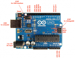
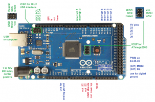
I don’t have Arduino Mega at hand, but google shows that SPI pins are different between Arduino Uno and Mega
http://www.ceezblog.info/images/blog/ArduinoMega2560_pinout.png
http://www.ceezblog.info/images/blog/ArduinoUno_R3_Pinouts.png
We need SPI (D11, D12, D13 of Uno) to communicate with SD card and sometime with the LCD TFT, but with this shield it uses 8-bit bus interface (LCD_D0 - LCD_D7) instead of SPI. That is why only LCD works but SD card doesn’t. But I think touchscreen should work too, because it needs 2 digital pins pull up to Vcc and 2 analog pins to get read of x-axis, y-axis of touch-point.
I have some sample codes in “Main library for LGDP4535” that should work with SD lib and CeezTouchScreen lib, you can check it out.
The touchscreen use 4 pins :
[code]#define YP A1
#define XM A2
#define YM 7
#define XP 6[/code]
Anyway, touchscreen has crap quality. So, don’t put high hope for this.
at 02:18:38
Thank you for your quick response. Yeah I didn’t have high hopes for the touchscreen. The SD would be nice though… I guess I will see about tracing out the holes on CON1 for being able to just breadboard with.
The weird thing I noticed is digital pin 11 shows activity on touchscreen presses. Which is labeled as part of the SD spi pins. I saw a bit from Adafruit about some of their shields sharing SPI for the touchscreen and SD. Still have some messing around to do then.
Thanks though!
at 17:38:47
thanks man :-) you saved me a lot of time! cheers….
Tuesday, August 4, 2015 at 01:43:16
I wrote a sketch that assists with calibration:
[code height=400]#include <Adafruit_GFX.h>
#include <LGDP4535.h>
#include <TouchScreen.h>
#define YP A3
#define XM A2
#define YM 9
#define XP 8
//My LCD Screen is
/*
#define TS_MINX 942
#define TS_MINY 963
#define TS_MAXX 172
#define TS_MAXY 170
*/
int TS_MINX = 0;
int TS_MINY = 0;
int TS_MAXX = 1023;
int TS_MAXY = 1023;
#define MINPRESSURE 10
#define MAXPRESSURE 1000
typedef struct {
int x;
int y;
} XY;
TouchScreen ts(XP, YP, XM, YM, 300);
#define BLACK 0×0000
#define WHITE 0xFFFF
LGDP4535 tft;
TSPoint getNextTouch() {
TSPoint point;
do {
digitalWrite(13, HIGH);
point = ts.getPoint();
digitalWrite(13, LOW);
pinMode(XM, OUTPUT);
pinMode(YP, OUTPUT);
}
while(!(point.z > MINPRESSURE && point.z < MAXPRESSURE));
return point;
}
TSPoint getNextRawTouch() {
TSPoint point;
do {
digitalWrite(13, HIGH);
point = ts.getRawPoint();
digitalWrite(13, LOW);
pinMode(XM, OUTPUT);
pinMode(YP, OUTPUT);
}
while(!(point.z > MINPRESSURE && point.z < MAXPRESSURE));
return point;
}
void setup() {
Serial.begin(9600);
tft.reset();
tft.begin();
ts.min_x = TS_MINX;
ts.min_y = TS_MINY;
ts.max_x = TS_MAXX;
ts.max_y = TS_MAXY;
ts.width = tft.width();
ts.height = tft.height();
ts.orientation = 0;
calibrate:
tft.fillScreen(BLACK);
tft.setTextColor(WHITE);
tft.setCursor(0, 0);
tft.println(”Screen Calibrationnn”
“Tap to Continue…”);
TSPoint point;
point = getNextRawTouch();
tft.fillScreen(BLACK);
tft.setCursor(0,0);
tft.print(”Slide in from the top.”);
point = getNextRawTouch();
tft.fillScreen(WHITE);
TS_MINY = point.y;
delay(100);
tft.fillScreen(BLACK);
tft.setCursor(0,0);
tft.print(”Slide in from the right.”);
point = getNextRawTouch();
tft.fillScreen(WHITE);
TS_MAXX = point.x;
delay(100);
tft.fillScreen(BLACK);
tft.setCursor(0,0);
tft.print(”Slide in from the bottom.”);
point = getNextRawTouch();
tft.fillScreen(WHITE);
TS_MAXY = point.y;
delay(100);
tft.fillScreen(BLACK);
tft.setCursor(0,0);
tft.print(”Slide in from the left.”);
point = getNextRawTouch();
tft.fillScreen(WHITE);
TS_MINX = point.x;
delay(100);
tft.fillScreen(BLACK);
ts.min_x = TS_MINX;
ts.min_y = TS_MINY;
ts.max_x = TS_MAXX;
ts.max_y = TS_MAXY;
tft.setCursor(0,0);
tft.println(”Your ADC calibrations values are:”);
tft.print(”TS_MINX = “);
tft.println(TS_MINX);
tft.print(”TS_MINY = “);
tft.println(TS_MINY);
tft.print(”TS_MAXX = “);
tft.println(TS_MAXX);
tft.print(”TS_MAXY = “);
tft.println(TS_MAXY);
tft.println();
tft.print(”The orientation of the touch screen should be zero with these values.n”
“Touch anywhere to test the screen. The coordinates will be in the upper left corner.”);
}
void loop() {
tft.setCursor(0,0);
tft.setTextColor(WHITE);
TSPoint p = getNextTouch();
tft.fillScreen(BLACK);
tft.print(’(');
tft.print(p.x);
tft.print(’,');
tft.print(p.y);
tft.print(’)');
delay(100);
}[/code]
It eliminates the need for touch screen rotation. You might need to change XP, YP, XM, and YM because I changed them from the original library to work with mine.
—-
edit by ceez:
Just add a mini toolbar to comment section
at 02:03:27
Very nice!
Thanks for the sketch.
I am sure many people will love this!
I will test it and put it in my post if i have your permision :)
I also like your thinking.
Anyway, I want to implement rotate feature in touchscreen lib in order to make it works better in lanscape mode. It’s not perfect yet. I will improve it when I have free time.
at 08:19:57
Great Job! I just ordered this PCB. Looks and fits like an Arduino shield, but there are no pictures to verify this. I have also read that this chipset/LCD requires 3.3 VDC. Is it safe to plug it into an Uno or a Leonardo?
Friday, August 7, 2015 at 11:02:21
Yes. It’s designed as a Uno shield and it should work fine like plug and play with the right library of course
at 17:15:16
I have the same TFT. It works great, I have several different display, but this is the best. It is bright, and the colours are good.
My works with these pin config with the original adafruit touch library.
#define YP A3
#define XM A2
#define YM 9
#define XP 8
The below pin config, which i think the original ones, not worked.
#define YP A1
#define XM A2
#define YM 7
#define XP 6
Try the alternate pin config.
Saturday, August 8, 2015 at 02:45:17
I have found a way to make the SD card work with an Arduino Mega. The problem is, that the shield is for an UNO, and the Mega uses other pins for the SD card.
I used the normal “SD.h” Library and my SD-setup looks as follows:
[code]//Setting up the SD card reader
Serial.print(”Initializing SD card…”);
if (!SD.begin(10, 11, 12, 13))
{
Serial.println(”initialization failed!”);
return;
}
Serial.println(”initialization done.”);[/code]
Im in no way pro at C++, but this works with my Data logger projekt.
at 02:47:29
Haha…it turned my code onto smilies
at 06:47:59
That is what tag [code] is invented for ;)
Monday, August 10, 2015 at 08:21:21
Thank you nangor! Thank you ceez
I picked up an UNO so I could try and use the shield touch and sd.
Touch is actually not bad on mine. Very easy and quite correct.
I ended up using the pinout nangor provided for it to work properly.
The calibration code that Nick provided returned the Min and Max values swapped. Once that was fixed everything works beautifully. The shield really does not like MEGA.
[code]
#define YP A3
#define XM A2
#define YM 9
#define XP 8
// your calibrated value should look like this
#define TS_MINX 174
#define TS_MINY 168
#define TS_MAXX 932
#define TS_MAXY 945
[/code]
Monday, August 17, 2015 at 04:10:39
Thank you! worked right out of the box for the 4535 display I received from ebay! saved me a lot of time. Thank you again :)
Wednesday, August 19, 2015 at 08:05:11
Working code for the Calculator example using the zTouchScreen library.
[CODE height=400]/***********************************************************
Example 6: Calculator
File version: 1.0
Update: using CeezTouchScreen lib
Description:
************************************************************/
#include <Adafruit_GFX.h> // Core graphics library
#include <LGDP4535.h> // Hardware-specific library
#include <zTouchScreen.h>
// Assign human-readable names to some common 16-bit color values:
#define BLACK 0×0000
#define BLUE 0×001F
#define RED 0xF800
#define GREEN 0×07E0
#define CYAN 0×07FF
#define MAGENTA 0xF81F
#define YELLOW 0xFFE0
#define WHITE 0xFFFF
// If using the shield, all control and data lines are fixed
LGDP4535 tft;
#define YP A1 // must be an analog pin, use “An” notation!
#define XM A2 // must be an analog pin, use “An” notation!
#define YM 7 // can be a digital pin
#define XP 6 // can be a digital pin
// your calibrated value should look like this
#define TS_MINX 120
#define TS_MINY 160
#define TS_MAXX 840
#define TS_MAXY 920
// un-comment this line to enable blue dot on touch point
//#define DEBUG
#define PENRADIUS 3
#define MINPRESSURE 10
#define MAXPRESSURE 1000
// For better pressure precision, we need to know the resistance
// between X+ and X- Use any multimeter to read it
// For the one we’re using, its 300 ohms across the X plate
TouchScreen ts = TouchScreen(XP, YP, XM, YM, 300);
int matrix[5][4]=
{{15,16,12,24},
{1,2,3,23},
{4,5,6,22},
{7,8,9,21},
{0,10,11,21}}
;
char matrixc[5][4]=
{{’O',’C',’<’,'/’},
{’1′,’2′,’3′,’*'},
{’4′,’5′,’6′,’-'},
{’7′,’8′,’9′,’+'},
{’0′,’.',’=',’ ‘}}
;
long result, input, mem;
byte op;
boolean in;
void setup(void) {
// initiate these variable for calculation correct point
// ts.min_x = TS_MINX;
// ts.min_y = TS_MINY;
// ts.max_x = TS_MAXX;
// ts.max_y = TS_MAXY;
// ts.width = 240;
// ts.width = 320;
// ts.orientation = 2; // rotate 180 degree
Serial.begin(9600);
Serial.println(F(”TFT LCD test”));
tft.reset();
uint16_t identifier = tft.readID();
Serial.print(F(”LCD driver chip: “));
Serial.println(identifier, HEX);
if (identifier == 0×4535)
Serial.println(F(”Using the library LGDP4535.nnPress the keypad to display number:”));
else Serial.println(F(”This is not the driver chip LGDP4535.nForce using library LGDP4535…”));
Serial.println();
tft.begin();
drawGUI();
input =0;
updateInput();
}
void drawGUI()
{
tft.fillScreen(BLACK);
int i,j;
for (i=0;i<=3;i++)
tft.drawFastHLine(1, 58+i*52, 238, WHITE);
tft.drawFastHLine(1, 58+4*52, 178, WHITE);
tft.drawFastHLine(1, 58+5*52, 238, WHITE);
for (i=0;i<=3;i++)
tft.drawFastVLine(1+i*59, 58, 266, WHITE);
tft.drawFastVLine(238, 58, 260, WHITE);
for (j=0;j<5;j++)
for (i=0;i<4;i++)
{
switch(matrixc[j][i])
{
case ‘O’:
tft.drawChar(58*i+14, 58+ 52*j+ 16, ‘A’, RED, BLACK, 3);
tft.drawChar(58*i+32, 58+ 52*j+ 16, ‘C’, RED, BLACK, 3);
continue;
case ‘<’:
tft.drawChar(58*i+14, 58+ 52*j+ 16, ‘<’, YELLOW, BLACK, 3);
tft.drawChar(58*i+29, 58+ 52*j+ 16, ‘-’, YELLOW, BLACK, 3);
continue;
case ‘+’:
tft.drawChar(58*i+22, 100+ 52*j, matrixc[j][i], YELLOW, BLACK, 3);
continue;
default:
tft.drawChar(58*i+22, 58+ 52*j+ 16, matrixc[j][i], YELLOW, BLACK, 3);
}
}
}
void updateInput()
{
tft.fillRect(1,10,240,40,BLACK);
tft.setCursor(1, 10),
tft.setTextColor(GREEN, BLACK);
tft.setTextSize(3);
tft.print(input);
}
void updateResult()
{
tft.fillRect(1,10,240,40,BLACK);
tft.setCursor(1, 10),
tft.setTextColor(GREEN, BLACK);
tft.setTextSize(3);
tft.print(result);
}
void updateOp()
{
tft.fillRect(220,10,240,40,BLACK);
tft.setCursor(220, 10),
tft.setTextColor(GREEN, BLACK);
tft.setTextSize(3);
if (op==1) tft.print(”+”);
if (op==2) tft.print(”-”);
if (op==3) tft.print(”*”);
if (op==4) tft.print(”/”);
}
void loop(void) {
// Recently Point was renamed TSPoint in the TouchScreen library
// If you are using an older version of the library, use the
// commented definition instead.
// Point p = ts.getPoint();
int x,y;
static int anterior=0, actual;
static unsigned long int tanterior=0, tactual=0;
TSPoint p = ts.getPoint();
//pinMode(XP, OUTPUT);
pinMode(XM, OUTPUT);
pinMode(YP, OUTPUT);
//pinMode(YM, OUTPUT);
// we have some minimum pressure we consider ‘valid’
// pressure of 0 means no pressing!
if (p.z > MINPRESSURE && p.z < MAXPRESSURE)
{
x=(4*p.x)/tft.width(); //0 - 3
y=(5*(p.y-52))/(tft.height()-52); // 0 - 5
actual=matrix[y][x];
tactual=millis();
if (tactual-tanterior>1000)
{
tanterior=tactual;
anterior=-1;
}
if (actual!=anterior )
{
Serial.println(actual);
anterior=actual;
//we got actual here as our touchpoint
switch (actual)
{
case 0:
case 1:
case 2:
case 3:
case 4:
case 5:
case 6:
case 7:
case 8:
case 9:
if (in ==false) input = 0;
in = true;
input= input*10 + actual;
updateInput();
break;
case 15: //AC
input=0;
mem =0;
result = 0;
op = 0;
in= true;
updateInput();
break;
case 16:
input = 0;
in = true;
updateInput();
break;
case 12:
// working on it later
input = input /10;
break;
case 21:
op = 1;
mem = input;
input = 0;
in = false;
updateOp();
break;
case 22:
op = 2;
mem = input;
input = 0;
in = false;
updateOp();
break;
case 23:
op = 3;
in = false;
mem = input;
input = 0;
updateOp();
break;
case 24:
op = 4;
mem = input;
input = 0;
in = false;
updateOp();
break;
case 11: // =
result = input;
if (op==1) result = mem + input;
if (op==2) result = mem - input;
if (op==3) result = mem * input;
if (op==4) result = mem / input;
op=0;
// input = 0;
mem= result;
in = true;
updateResult();
break;
}
#ifdef DEBUG
tft.fillCircle(p.x, p.y, PENRADIUS, BLUE);
#endif
}
}
}[/CODE]
at 18:11:51
Actually, it worked, but I update the zTouchScreen lib and forgot to update these examples in the TFT-LGDP4535 lib.
I think access variables directly like that would not be a good practice in C++ generally. So I put up a function to do the job.
[CODE]ts.InitVariable(0, 240, 320, TS_MINX, TS_MAXX, TS_MINY, TS_MAXY, MINPRESSURE, MAXPRESSURE);[/CODE]
Read README.txt and header file for more info about public function that you can use.
Thursday, August 27, 2015 at 02:45:18
Display works great, thanks Ceez!
However, TScalibration returns (1023, 1023, 1023, 1023) which obviously doesn’t make much sense… Any ideas what may be the problem?
at 03:03:34
One thing comes up: wrong pin config for touchscreen
Try
#define YP A3
#define XM A2
#define YM 9
#define XP 8
You can use a VOM meter to trace the pins of touchscreen.
Or try to find 2 pairs of pins which have about 300 Ohm across each pair
at 04:59:09
Great, that worked. I also had to modify TouchScreen::getRawPoint(void) because my pressure value was inverted: z = 1023 - rtouch;
Thanks again Ceez, you rock!
Monday, September 7, 2015 at 17:56:00
Hey Ceez,
I tested the display with all of your files from your post. I tried to run the calculator example from user Jason Church here, but for me is it not possible to have the touch feature on the correct positions. I think there is some parameters not fine for my touchpad.
I use the same panal as you and I’m happy if you could give a short statement about that.
Thanks allot for your post here. This is the first useful page withe information about that lcd.
Best regards
Mia
Tuesday, September 8, 2015 at 16:21:47
Yours may look exactly the same, but I think the touch screen pins are different.
Unfortunately, there is no labels on the shield that indicates touchscreen pins.
For me, it is:
[code]#define YP A1
#define XM A2
#define YM 7
#define XP 6[/code]
For you, it might be:
[code]#define YP A3
#define XM A2
#define YM 9
#define XP 8[/code]
Like I said to John M, you can use a VOM meter to trace the pins of touchscreen, or try to find 2 pairs of pins which have about 300 Ohm across each pair.
I will update my post with this infos when I have some free time.
Have fun,
Wednesday, September 9, 2015 at 15:34:06
Hey Ceez,
thank you allot. I measured 400 Ohm between theese pins, but I’ll try to take a look again for this. You’re right with the pins A3/A2/9/8. That is exactly the configuration I used in my code:
[code height=400]
/***********************************************************
Example 6: Calculator
File version: 1.0
Update: using CeezTouchScreen lib
Description:
************************************************************/
#include <Adafruit_GFX.h> // Core graphics library
#include <LGDP4535.h> // Hardware-specific library
#include <zTouchScreen.h>
// Assign human-readable names to some common 16-bit color values:
#define BLACK 0×0000
#define BLUE 0×001F
#define RED 0xF800
#define GREEN 0×07E0
#define CYAN 0×07FF
#define MAGENTA 0xF81F
#define YELLOW 0xFFE0
#define WHITE 0xFFFF
// If using the shield, all control and data lines are fixed
LGDP4535 tft;
#define YP A3 // must be an analog pin, use “An” notation!
#define XM A2 // must be an analog pin, use “An” notation!
#define YM 9 // can be a digital pin
#define XP 8 // can be a digital pin
// your calibrated value should look like this
#define TS_MINX 120
#define TS_MINY 160
#define TS_MAXX 840
#define TS_MAXY 920
// un-comment this line to enable blue dot on touch point
//#define DEBUG
#define PENRADIUS 3
#define MINPRESSURE 10
#define MAXPRESSURE 1000
// For better pressure precision, we need to know the resistance
// between X+ and X- Use any multimeter to read it
// For the one we’re using, its 300 ohms across the X plate
TouchScreen ts = TouchScreen(XP, YP, XM, YM, 400);
int matrix[5][4] =
{ {15, 16, 12, 24},
{1, 2, 3, 23},
{4, 5, 6, 22},
{7, 8, 9, 21},
{0, 10, 11, 21}
}
;
char matrixc[5][4] =
{ {’O', ‘C’, ‘<’, ‘/’},
{’1′, ‘2′, ‘3′, ‘*’},
{’4′, ‘5′, ‘6′, ‘-’},
{’7′, ‘8′, ‘9′, ‘+’},
{’0′, ‘.’, ‘=’, ‘ ‘}
}
;
long result, input, mem;
byte op;
boolean in;
void setup(void) {
// initiate these variable for calculation correct point
// ts.min_x = TS_MINX;
// ts.min_y = TS_MINY;
// ts.max_x = TS_MAXX;
// ts.max_y = TS_MAXY;
// ts.width = 240;
// ts.width = 320;
// ts.orientation = 0; // rotate 180 degree
Serial.begin(9600);
Serial.println(F(”TFT LCD test”));
tft.reset();
uint16_t identifier = tft.readID();
Serial.print(F(”LCD driver chip: “));
Serial.println(identifier, HEX);
if (identifier == 0×4535)
Serial.println(F(”Using the library LGDP4535.nnPress the keypad to display number:”));
else Serial.println(F(”This is not the driver chip LGDP4535.nForce using library LGDP4535…”));
Serial.println();
tft.begin();
drawGUI();
input = 0;
updateInput();
}
void drawGUI()
{
tft.fillScreen(BLACK);
int i, j;
for (i = 0; i <= 3; i++)
tft.drawFastHLine(1, 58 + i * 52, 238, WHITE);
tft.drawFastHLine(1, 58 + 4 * 52, 178, WHITE);
tft.drawFastHLine(1, 58 + 5 * 52, 238, WHITE);
for (i = 0; i <= 3; i++)
tft.drawFastVLine(1 + i * 59, 58, 266, WHITE);
tft.drawFastVLine(238, 58, 260, WHITE);
for (j = 0; j < 5; j++)
for (i = 0; i < 4; i++)
{
switch (matrixc[j][i])
{
case ‘O’:
tft.drawChar(58 * i + 14, 58 + 52 * j + 16, ‘A’, RED, BLACK, 3);
tft.drawChar(58 * i + 32, 58 + 52 * j + 16, ‘C’, RED, BLACK, 3);
continue;
case ‘<’:
tft.drawChar(58 * i + 14, 58 + 52 * j + 16, ‘<’, YELLOW, BLACK, 3);
tft.drawChar(58 * i + 29, 58 + 52 * j + 16, ‘-’, YELLOW, BLACK, 3);
continue;
case ‘+’:
tft.drawChar(58 * i + 22, 100 + 52 * j, matrixc[j][i], YELLOW, BLACK, 3);
continue;
default:
tft.drawChar(58 * i + 22, 58 + 52 * j + 16, matrixc[j][i], YELLOW, BLACK, 3);
}
}
}
void updateInput()
{
tft.fillRect(1, 10, 240, 40, BLACK);
tft.setCursor(1, 10),
tft.setTextColor(GREEN, BLACK);
tft.setTextSize(3);
tft.print(input);
}
void updateResult()
{
tft.fillRect(1, 10, 240, 40, BLACK);
tft.setCursor(1, 10),
tft.setTextColor(GREEN, BLACK);
tft.setTextSize(3);
tft.print(result);
}
void updateOp()
{
tft.fillRect(220, 10, 240, 40, BLACK);
tft.setCursor(220, 10),
tft.setTextColor(GREEN, BLACK);
tft.setTextSize(3);
if (op == 1) tft.print(”+”);
if (op == 2) tft.print(”-”);
if (op == 3) tft.print(”*”);
if (op == 4) tft.print(”/”);
}
void loop(void) {
// Recently Point was renamed TSPoint in the TouchScreen library
// If you are using an older version of the library, use the
// commented definition instead.
// Point p = ts.getPoint();
int x, y;
static int anterior = 0, actual;
static unsigned long int tanterior = 0, tactual = 0;
TSPoint p = ts.getPoint();
//pinMode(XP, OUTPUT);
pinMode(XM, OUTPUT);
pinMode(YP, OUTPUT);
//pinMode(YM, OUTPUT);
// we have some minimum pressure we consider ‘valid’
// pressure of 0 means no pressing!
if (p.z > MINPRESSURE && p.z < MAXPRESSURE)
{
x = (4 * p.x) / tft.width(); //0 - 3
y = (5 * (p.y - 52)) / (tft.height() - 52); // 0 - 5
actual = matrix[y][x];
tactual = millis();
if (tactual - tanterior > 1000)
{
tanterior = tactual;
anterior = -1;
}
if (actual != anterior );
{
Serial.println(actual);
anterior = actual;
//we got actual here as our touchpoint
switch (actual)
{
case 0:
case 1:
case 2:
case 3:
case 4:
case 5:
case 6:
case 7:
case 8:
case 9:
if (in == false) input = 0;
in = true;
input = input * 10 + actual;
updateInput();
break;
case 15: //AC
input = 0;
mem = 0;
result = 0;
op = 0;
in = true;
updateInput();
break;
case 16:
input = 0;
in = true;
updateInput();
break;
case 12:
// working on it later
input = input / 10;
break;
case 21:
op = 1;
mem = input;
input = 0;
in = false;
updateOp();
break;
case 22:
op = 2;
mem = input;
input = 0;
in = false;
updateOp();
break;
case 23:
op = 3;
in = false;
mem = input;
input = 0;
updateOp();
break;
case 24:
op = 4;
mem = input;
input = 0;
in = false;
updateOp();
break;
case 11: // =
result = input;
if (op == 1) result = mem + input;
if (op == 2) result = mem - input;
if (op == 3) result = mem * input;
if (op == 4) result = mem / input;
op = 0;
// input = 0;
mem = result;
in = true;
updateResult();
break;
}
#ifdef DEBUG
tft.fillCircle(p.x, p.y, PENRADIUS, BLUE);
#endif
}
}
}
[/code]
I’m a beginner in coding for arduino and will check again. The touch funktion works, but the positions of the touches are wrong.
I think it’s only a little thing I missed in the code.
After testing I would write here and give you a featback about that.
Best regards
Mia
Thursday, September 10, 2015 at 16:48:22
Put this line
[CODE]ts.InitVariable(0, 240, 320, TS_MINX, TS_MAXX, TS_MINY, TS_MAXY, MINPRESSURE, MAXPRESSURE);[/CODE]
in function [COLOR=#008000]void [/COLOR][COLOR=#0000ff]setup [/COLOR]([COLOR=#008000]void[/COLOR])
I changed the way initialize these variables. Use the code above instead.
It doesn’t make sense when you declare these variable but you don’t use them :)
And change
[code]// un-comment this line to enable blue dot on touch point
//#define DEBUG[/code]
to
[code]// un-comment this line to enable blue dot on touch point
#define DEBUG[/code]
There is a file readme that shows how to use and sample code for zTouchScreen
You can find sample calculator v1.1 in the new update of LGDP4535 library
Friday, September 11, 2015 at 16:16:22
Thank you so much :-)
As I said, I’m a beginner and now I able to start with my own code for some projects.
In[CODE] ts.InitVariable(2, 240, 320, TS_MINX, TS_MAXX, TS_MINY, TS_MAXY, MINPRESSURE, MAXPRESSURE);[/CODE]
I use the rotation for 180 degree. Maybe I changed it in the <zTouchScreen.h>.
Thank you again. You’re blog is saved in my browser ;-)
Mia
Saturday, September 26, 2015 at 07:53:58
still cant get mine to work white screen
Monday, September 28, 2015 at 12:37:18
Are you sure yours is lgdp4535 one ?
Thursday, October 15, 2015 at 08:14:36
Hey Ceez!
Does this touchscreen support sensing pressure for a touch?
Thanks,
Mihir
at 08:29:19
In the software yes. But in the hardware, I don’t think so. Its a resistive touch screen, cheap one. One finger, two fingers or the whole palm, it still registers as one single point with some dummy pressusure value. Totally not reliable.
Ceez
Saturday, October 17, 2015 at 08:58:02
Hi Ceez,
Thank you again so much for your wonderful work. I got my LG4535 TFT LCD working with some modification of your code. I have also made it work with JOS menu system.
I have post it on my site, hope it will help someboday.
http://tech.memoryimprintstudio.com/arduino-with-a-lgdp4535-tft-lcd-touch-screen/
Tony
———————————–
Memory Imprint Studio
Tuesday, November 3, 2015 at 09:32:46
Did anybody here make the SD card work with Arduino Mega 2560? I have no problem with Uno, but lost with Mega.
Thanks in advance for any help.
Tony
at 11:00:38
As I stated in comment #15, thing is not going to be easy.
Most shields are designed for Arduino Uno and doesn’t work well on Arduino Mega or even doesn’t work at all.
I don’t have Arduino Mega at hand, but google shows that SPI pins are different between Arduino Uno and Mega
http://www.ceezblog.info/images/blog/ArduinoMega2560_pinout.png
http://www.ceezblog.info/images/blog/ArduinoUno_R3_Pinouts.png
SD card using SPI (hardware SPI - D11, D12, D13 on Uno) to transfer data and some LCD TFT displays use SPI too, but this shield it uses 8-bit bus interface (LCD_D0 - LCD_D7) instead of SPI. That is why only LCD works but SD card doesn’t.
So, I think you need to use software SPI, modify the SD library to use software SPI on digital pins located at the same place as SPI pins on UNO board.
Ask Mr. Google “software SPI”, he give some interesting stuffs like
http://little-scale.blogspot.com.au/2007/07/spi-by-hand.html
or https://github.com/niteris/ArduinoSoftSpi
Wednesday, November 4, 2015 at 04:40:30
Ceez,
awesome, great work…
Sounds very good. I’ll give em another try just in a few minutes. :-)
Thank you very much.
Br
Guido
at 06:43:06
Thanks for the info, Ceez. This is a tough one. I follow instruction here https://learn.adafruit.com/2-8-tft-touch-shield/bitmaps, more here (https://www.arduino.cc/en/Reference/SDCardNotes), and Adafruit’s SD library (https://github.com/adafruit/SD) with soft SPI. Still no luck. should work though. Guildo, Please post back if you had a better luck.
Tony
at 09:48:19
Take a quick look on the SPI library SPI.h, SPI.cpp (hardware/arduinoavr/librariesSPI) and I find nothing for SOFTWARE SPI. My Arduino IDE version is 1.65. So, [S]I suspect the SD lib from adafruit won’t work either, even they have some config option for changing the SPI pins for using SOFTWARE SPI.[/S]
I take back what I said. I saw some SPI bitbang functions in SD-master/utility/Sd2Card.cpp look like the same code as TFT display ST7753
[CODE]inline void ST7735::spiwrite(uint8_t c)
{
//Serial.println(c, HEX);
if (hwSPI) { // if using Hardware SPI
SPI.transfer(c);
} else { // if not using Hardware SPI
// Fast SPI bitbang swiped from LPD8806 library <— COPY AND PASTE ???
for(uint8_t bit = 0×80; bit; bit >>= 1) {
if(c & bit) dataport->PIO_SODR |= datapinmask;
else dataport->PIO_CODR |= datapinmask;
clkport->PIO_SODR |= clkpinmask;
clkport->PIO_CODR |= clkpinmask;
}
}
}[/CODE]
And this code is found on SD-master/utility/Sd2Card.cpp
[CODE] static void spiSend(uint8_t b) {
if (clockPin_ == -1) {
#ifndef USE_SPI_LIB
SPDR = b;
while (!(SPSR & (1 << SPIF)));
#else
SPI.transfer(b);
#endif
} else {
noInterrupts();
// Fast SPI bitbang swiped from LPD8806 library <— COPY AND PASTE ???
for (uint8_t i = 0; i < 8; i++) {
*clkport &= ~clkpinmask;
if (b & 0×80)
*mosiport |= mosipinmask;
else
*mosiport &= ~mosipinmask;
*clkport |= clkpinmask;
b <<= 1;
}
nop;nop;nop;nop;
*clkport &= ~clkpinmask;
interrupts();
}
}[/CODE]
That is funny, it look like the job of copy and paste :D . Anyway, I think it should work. Sorry I can’t be more helpful since I don’t have a Mega board at hand.
at 17:14:51
Thanks Ceez, I will post back if I have a better luck.
Tony
Saturday, November 7, 2015 at 18:32:37
Hi Ceez,
Got it working, finally. You were right! I post the step here http://tech.memoryimprintstudio.com/access-sd-cards-from-tft-lcd-shield-using-arduino-mega-2560-soft-spi/.
Thanks again.
Tony
——————————–
Memory Imprint Studio
Sunday, November 8, 2015 at 04:06:05
Glad to hear that. I will update my post for Mega board user :)
Thursday, November 12, 2015 at 15:33:06
Can you explain where the text “rotate” is found. I have my screen in landscape and text is in portrait? the default demo rotates the whole screen but “https://learn.adafruit.com/downloads/pdf/2-8-tft-touchscreen.pdf” suggests there is a rotate command? thanks
at 19:39:22
You make me confuse. Are you talking about the function setRotation()?
According to the guide using TFT screen, there is a function name “rotate()” which I am pretty sure doesn’t exist in the library LGDP4535.
Are you trying to draw a vertical text line along with horizone text line at the same time or trying to do something like that?
Friday, November 13, 2015 at 18:00:22
Hi Ceez,
Can you give some general guidance on how to make this library work with LGDP4535? https://github.com/ginge/GuiLibrary It uses Adafruit core library.
Thanks
Tony
Sunday, November 15, 2015 at 06:41:15
@Tony: I will take a look some other times
Monday, November 16, 2015 at 05:16:19
Thanks, Ceez. I got the display working fine. Fixing the touch screen coordinate now. Will keep you updated.
Tony
Wednesday, December 30, 2015 at 03:40:00
Thank you, your modification just did it!
I was struggling with this TFT shield, had the same impression, when bought, it’s a shield, just plug in in and have fun, I was sooo wrong, but you did it!
Thursday, December 31, 2015 at 23:25:23
Pingback from http://thdarduino.blogspot.de/2015/12/freeduino-serial-v20-bausatz.html
Sunday, January 3, 2016 at 21:06:59
Works perfect.
For paint example I had to modify reverse by removing tft.width()- in
p.x = tft.width()-(map(p.x, TS_MINX, TS_MAXX, tft.width(), 0));
Thans!
Friday, January 15, 2016 at 07:38:19
I would like to know how many pins are free so I can work with them and if the I2C is functional? I noted that on Arduino Uno even if I don’t use the sdcard function I can’t use pin #3. Thanks for your hard work!
Wednesday, April 6, 2016 at 18:04:45
Hi I read your article and find it was very helpful. I bought and china brand tft and have no idea what the driver model, can please email me the code to display the driver name on the serial monitor like above thx in advance
at 20:46:14
First, you need to know your TFT LCD uses SPI or 8bit/16bit parallel or i2c connection. It is easy: judge from the labels of the pins, it says SDA, SCK or SCLK, MOSI, MISO or D0, D1, D2…D7 so you will know it uses what kind of connection.
Then you search for a library that support that kind of connection, even it is not meant for your TFT LCD. The library will provide some functions that send/receive data to the LCD include a fuction that will read ID of TFT LCD, something like
[CODE]LGDP4535 tft;
void setup(void) {
Serial.begin(9600);
Serial.println(F(”TFT LCD test - Graphic Test”));
tft.reset();
uint16_t identifier = tft.readID();
Serial.print(F(”LCD driver chip: “));
Serial.println(identifier, HEX);[/CODE]
You will find similar code in the samples of that library.
Once you can make your TFT LCD talks, everything become easier unless your TFT LCD uses a graphic driver that no library has been written for it yet.
One more thing, most TFT LCD only accepts 3v3 TTL signal, 5v TTL signal from Arduino won’t work but lucky it won’t kill the LCD.
Monday, April 11, 2016 at 13:06:07
Hi the model is 0×0303 tft lcd a china-brand lcd kedei taobao link below
https://world.taobao.com/item/45209966331.htm?fromSite=main&spm=a312a.7700824.w4004-10821130036.21.LxChK4
I tried many tft lcd library when i connect it to my arduino MEGA and not much success.
thx in advance
Tuesday, April 12, 2016 at 18:53:40
Judge on the link, it is 8 bit parallel one.
Have you tried this library https://forum.arduino.cc/index.php?topic=327294.msg2292602#msg2292602 yet ?
I’ve just take a quick look at the code, and found example RGB_TO_565 just like the picture on Taobao. I beleive this library is the right one for you.
Anyhow, you said not much success, and you got the LCD ID 0×0303. I think you actually got some code that works, proof is you success comunicate with your TFT LCD. All you need now is the right initialization code to “start-up” your TFT LCD.
Thursday, May 19, 2016 at 23:20:37
I had bought a TFT from amazon (FOXNOVO) and i have tried multiple libraries with no luck. All I get is an empty white screen. How can I test that is only the library and nothing else is wrong
Friday, May 20, 2016 at 20:11:59
Did you try to listen on serial port for debug information of the sample sketch, or even better, the ID of the TFT screen?
As far as I know, TFT shield usually uses parallel connection or SPI connection. Mostly cheap TFT shields use 8-bit parallel connection. Check the label of pins on the back for connection type. usually the command to get the ID is the same to most of TFT shield. If you can get the ID everything will be easier.
To be honest, it is almost no way to tell if the tft still work or fail, except you are able to communicate to the tft screen. Assume yours is a tft shield, yes? Then there are 2 things should take in account: wrong library and yours is not Arduino Uno but arduino mega or leonardo or something else.
Saturday, May 21, 2016 at 01:25:37
The TFT is shielded and it looks identical to the one on the picture here. The board is arduino uno R3 from Robotlink. The pins are identical to the UNO board (also confirmed that). I downloaded the libraries here and tried the ID sketch sample with no luck. It just stays blank.
Monday, May 23, 2016 at 22:42:09
1/ Double check if the label of the pins on your the TFT shield are in exact order to the one in picture. Picture is better.
2/ If “YES” then try sample “graphicstest” and tell me if it shows “LCD driver chip: 0×4535”. Again picture is better.
I doubt it will show 0×4535 for the chip ID. Or maybe It doesn’t show anything on serial monitor at all.
If “NO” for either one of two questions, I am unable to help you since the only TFT shield I have is this TFT with 4535 chipset. You need professional help like this guy https://forum.arduino.cc/index.php?topic=366304.msg2524865#msg2524865
Anyway, It won’t go anywhere without knowing the exact chipset of your TFT shield or just trying random libraries from the internet while crossing your fingers.
Tuesday, October 25, 2016 at 06:39:28
Hello, and thanks for your work, my problem is that i cant make it work with my arduino Mega, i’ve used your libraries as i have the lgdp4535 chip, and used the pins 22 to 29 to connect the LCD, and included the mega_24_shield.h but it doesnt work, can you tell me what am i doing wrong?
Thanks beforehand.
at 21:21:47
It doesn’t compile or it compiles and shows white screen?
Are you sure yours is 4535? Run example and open serial monitor (9600 baud rate) and see the results.
Read comments above. I know it’s long, but the answer’s probably up there.
Or you’ll another tutorial on Mega board here http://tech.memoryimprintstudio.com/arduino-with-a-lgdp4535-tft-lcd-touch-screen/
Wednesday, October 26, 2016 at 06:13:05
Yeah, about that i didnt give u much information. Sorry!
It can compile. The screen shows white screen, i used an LCD ID Reader that says it is the 0×4535 so i assume it is the correct chip, but i checked it out with the “paint” example and it says “TFT LCD test - TFT Paint
LCD driver chip: 0
This is not the driver chip LGDP4535.
Force using library LGDP4535…”
and with that i dont know what to do…
I did the steps to use an arduino mega in the post that you attached but the screen remains blank, and i read all the comments above and couldnt find the same case that i have.
at 06:16:02
Oh i have to add that i used this TFT in an Arduino UNO and it worked (just that one axis was inverted) with your programs.
at 07:55:43
If it works on UNO, it should works on Mega unless your Mega has (some) dead IO pin(s). And this would prevent Mega board communicates with the TFT if that pin is used for transferring data. It is worst case scenario, other than that maybe there is bug in mega_24_shield.h that use to pin mapping for Mega board and it maps the wrong pin in used. As you might know, these pin mapping are very much different on these 2 boards. But this case is less likely to happen.
So, I am not really sure, and I don’t have a Mega board to check it out.
PS: for me I just use this shield for experiment and then toss it aside when I am done. I only use breakout modules which I specifically choose a type of connectivity (spi or i2c). This way, easier to debug if things go wrong.
at 08:06:27
i got the Display problem solved, now it works partially ok. But now i have a problem with my X axis, its inverted xD, do you know how can i solve it?
at 15:28:53
Try Arduino-TSCalibration.rar and then apply new values for your sketch.
http://ceezblog.info/2015/04/20/240%78320-28-tft-shield-driver-4535-for-arduino/#download
It would fix the touch region and also reversed axis if there is.
Thursday, November 17, 2016 at 16:25:00
can you post pin description of ILI9341 2.8” TFT display?
Thanks in advance.
at 18:04:24
I am sorry I don’t have an ili9341 TFT shield. In fact, I won’t buy any TFT shield. This is the only one I bought for experiment, learning purpose. Thus, I couldn’t help you with this. But if you are looking for pinout of breakout TFT display, it should have label right next to the pins.
This may sound not logic, but a breakout TFT with SPI connection are way better than a shield as you will save a great deal of time solving troubles. The shield thing only works as if it is genuine product from arduino company or some companies like sparkfun or adafruit, of course with much higher price than a random seller on ebay or amazon.
Sunday, November 27, 2016 at 04:26:58
The sield uses most pins, only a few left - what about the connection labeled {COM1} at the end of the board? What is it for? Can it be used as a “break-out” connection for the display, to free up the pins on the Uno?
Monday, November 28, 2016 at 17:00:24
Sorry, but I have no idea what are you talking about. If you want some free IO pins, use TFT with SPI connection instead.
Wednesday, November 30, 2016 at 09:12:33
My board is labeled HXJ002 rather than mcufriend, and identifies as an ILI8341. There are 18 open solder pads (2×9) on the end of the circuit board, where it extends past the glass, labeled COM1. Most appear to go to the ribbon cable connector, with a couple going to U2/U3 and at least 1 to the SD.
Is it possible to identify these pins? I suspect this would be the pins for a Mega, which shows a header across its end perpendicular to the normal Uno headers.
at 10:56:34
Correction — ILI9341.
Friday, December 2, 2016 at 20:08:08
I see what you mean
I think they are extra pins for 18bit interface, 16bit interface (D8 to D17) and SPI interface of the driver chip ili9341 (LGDP4535 has these interfaces too). Those pins go to SD card must be SPI pins of the driver, but I guess it connect to D13, D12, D11 on Arduino via level shifter U2.
If you can trace these pins CON1 to the yellow flex cable and also has the pinout of the that flex cable, you can determine what function of these pins. And so you can change the interface of your TFT following the datasheet of ili9341 page 26 https://cdn-shop.adafruit.com/datasheets/ILI9341.pdf . And yes, if you can find pin IM0 to IM3 of the the TFT driver you are able to use this shield as an breakout board by forcing it to run on SPI interface.
Never done this nor having that much curiosity to take control completely of the TFT shield, just some possibilities that I can think of, but anyhow these pins are pretty much useless to me as it takes to much effort to use these pins. Anyway, you can get a breakout TFT screen with SPI interface for half price of the TFT shield.