For the first time having experience with arduino and TFT screen, a TFT display shield should be better than a breakout TFT display, because a shield is something that made for plug-n-play, like a usb thing, just plug it in the computer and it works right away.
That what I thought when I bought this shield.
But I was wrong.
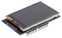
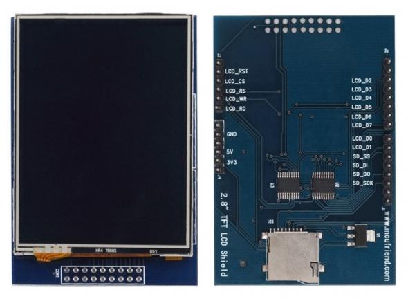
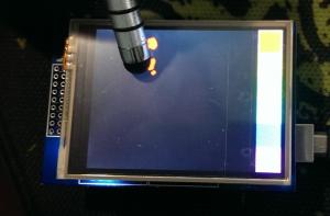
It is the cheap TFT display you will get from ebay. There are serveral models using different drivers - mine uses LGDP4535 - that looks like the picture above.
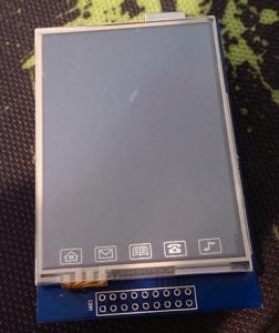
In fact they add some extra features to the one I bought:
It’s really stupid with these Icons. It looks like the touch screen of a cheap-crappy-chinese phone. However, I managed to remove that and leave a clean TFT screen. It is quite easy. The touch screen made of a piece of glass that sticks to the underneath screen using sticky tape instead of bezel frame. Just lift the glass up and it comes out. But one problem: you have to use double side sticky tape to replace the tape you take out. For me, I will use silicon to stick the touch screen to the TFT screen. Mean while, I use clear sticky tape to stick the touchy-glass to the whole thing.
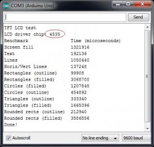
I searched google and tried several libraries and sample codes but non-success, all I could do is get the LCD driver chip id: 0×4535 and a blank white screen until I found a thread on forum.arduino.cc for the same TFT LCD shield brand name www.mcufriend.com.
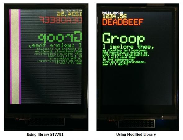
I tried the library for the driver ST7781 from SWTFT and amzingly the screen works, barely :D . The screen is mirror and 1/6 of it on the left side just show rubbish. For the first time, it works, technically, not fully functioning but at least it shows something.
I did more search on the chip 4535 and finally found the datasheet and application note of this chip LGDP4535 from LG! So, I took the Initialization command found on datasheet and put it in the barely-woking library and voila everything becomes perfect.
Other people on arduino have the exactly look alike LCD shield like mine, but it comes with the chip ST7781, ST7783 or HX8347… which someone already wrote libraries for them.
When I try the touch screen, I find out that the default TouchScreen has the Zero point (0,0) located in the bottom-right corner not top-left like the LCD. I added rotation ability to the TouchScreen library and renamed it to zTouchScreen.
Of course, I have to calibrate the limit of the touch screen.
My litmit X,Y look like this
#define TS_MINX 840
#define TS_MINY 820
#define TS_MAXX 120
#define TS_MAXY 160
It looks strange when Max_X is smaller than Min_X. The thing is this helps rotate the screen 180 degree.
At first, I tried some random numbers, uploaded the sketch and tried the touch screen. Did it again until everything seem ok. Well, It’s kinda suck when I have to do it manually.
There are other ways to calibrate this touch-screen like this link or use the sketch at the end of this post. Thanks Nick for the sketch that helps a lot in calibration.
After a while playing with it, I realize this is resistive touch screen, not capacitive touch screen. I can use a pointy stylus to get more accuracy touch point, but it still sucks.
Some people report that touch screen pins are different in their TFT shield
Mine is:
#define YP A1
#define XM A2
#define YM 7
#define XP 6
Others is
#define YP A3
#define XM A2
#define YM 9
#define XP 8
When using zTouchScreen, remember to initialize these variables:
ts.InitVariable(rotate, width, height, TS_MINX, TS_MAXX, TS_MINY, TS_MAXY, MINPRESSURE, MAXPRESSURE);Width and Height are the in the default orientation, for this shield it is rotate = 0 and and width = 240, height = 320. If you want to rotate the screen 90 degree, just put rotate = 1, but width and height still the same (240 and 320).
The last test is displays an 24bit bitmap image using SD lib
[ANCHOR=download]Download
[attach=download/TFT-LGDP4535.rar]TFT-LGDP4535.rar[/attach] - Main library for LGDP4535 - Updated 2015/8/19
[attach=download/Adafruit_GFX.rar]Adafruit_GFX.rar[/attach] - Graphic library for rendering
[attach=download/LGDP4535_datasheet.rar]LGDP4535_datasheet.rar[/attach] - Driver chip LGDP4535 datasheet
[attach=download/zTouchScreen.rar]zTouchScreen.rar[/attach] - Modified TouchScreen Library - Updated 2015/8/5
[attach=download/Arduino-TSCalibration.rar]Arduino-TSCalibration.rar[/attach] sketch that used for touch screen calibration - Thanks Nick
———————————————————–
Update 2015/11/8:
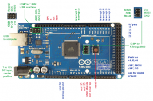
For Arduino Mega user, the SD card is not going to work, because SD card module on this shield is using Hardware SPI
Fortunately, the display still works fine, because this TFT display using 8-bit bus interface (LCD_D0 to LCD_D7) instead of SPI.
So, what can we do?
Luckily, there is solution for this problem by using software SPI
Open this file Arduino/libraries/SD/src/utility/Sd2Card.h
You will see some interesting information from line 34
/**
 * USE_SPI_LIB: if set, use the SPI library bundled with Arduino IDE, otherwise
 * run with a standalone driver for AVR.
 */
#define USE_SPI_LIB
/**
 * Define MEGA_SOFT_SPI non-zero to use software SPI on Mega Arduinos.
 * Pins used are SS 10, MOSI 11, MISO 12, and SCK 13.
 *
 * MEGA_SOFT_SPI allows an unmodified Adafruit GPS Shield to be used
 * on Mega Arduinos.  Software SPI works well with GPS Shield V1.1
 * but many SD cards will fail with GPS Shield V1.0.
 */
#define MEGA_SOFT_SPI 0
So, you need to change it to
/* #define USE_SPI_LIB */    // commented out
#define MEGA_SOFT_SPI 1 // change to 1 from 0
Thanks Tony for this found
[tag]TFT shield LGDP4535[/tag]
